Cylinder Head: Removal: Removal
WARNING: This page is about a different variant/trim than selected.
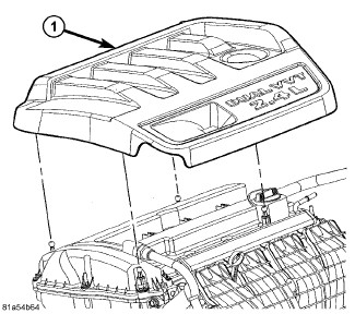
- Remove the engine cover (1) by pulling upward.
- Perform the fuel system pressure release procedure. Refer to FUEL SYSTEM PRESSURE RELEASE PROCEDURE .
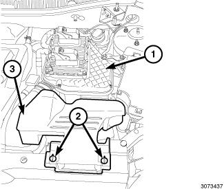
- Unlock the retainers (2) and remove the fresh air inlet duct (3) from air cleaner body (1).
- Disconnect and isolate the negative battery cable.
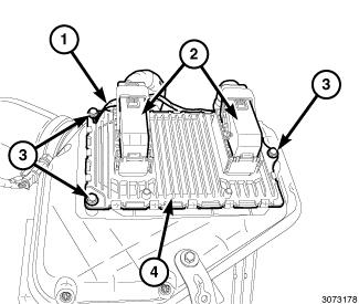
- Unlock and disconnect the electrical connectors (2) from the PCM (4).
- Remove the mounting bolt (3) and ground wire (1).
- Remove the air inlet tube (2) from the air cleaner body (1).
- Disconnect the make-up air hose (3) from the air cleaner body.
- Remove the support bracket bolt from the strut tower.
- Pull upward to disengage the pins from the rubber grommets and remove the air cleaner body (1).
- Drain the cooling system. Refer to STANDARD PROCEDURE .
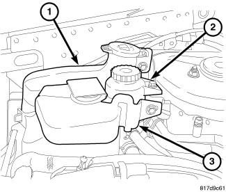
- Remove the coolant recovery bottle (3). Refer to BOTTLE, COOLANT RECOVERY, REMOVAL .
- Remove and reposition power steering reservoir (2).
- Remove windshield washer bottle (1). Refer to RESERVOIR, WINDSHIELD WASHER, REMOVAL .
- Remove accessory drive belt. Refer to BELT, SERPENTINE, REMOVAL .
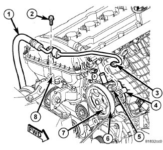
- Remove power steering hose hold down (2).
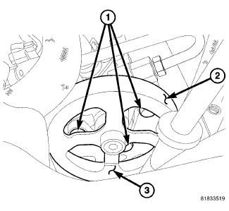
- Remove the three power steering pump mounting bolts (1) through the openings in the pulley (3) and reposition the pump.
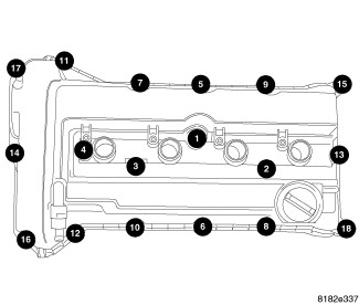
- Remove the cylinder head cover. Refer to COVER(S), CYLINDER HEAD, REMOVAL .
- Remove ignition coils from cylinder head cover.
- Raise and support the vehicle. Refer to HOISTING, STANDARD PROCEDURE .
- Remove the right splash shield. Refer to SHIELD, SPLASH, FRONT WHEELHOUSE, REMOVAL .
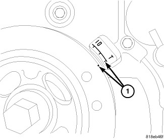
- Set engine to TDC (1).
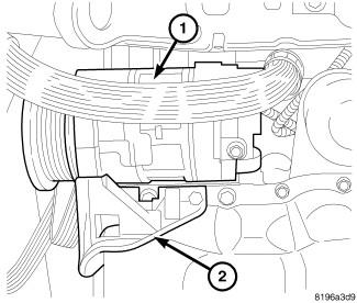
- Remove lower A/C compressor bolts if equipped.
- Remove lower A/C compressor mount (2) if equipped.
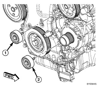
- Remove accessory drive belt lower idler pulley (2).
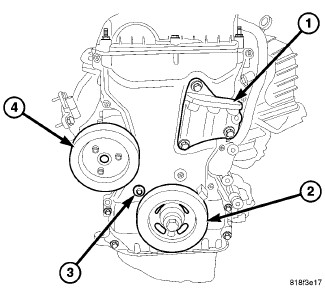
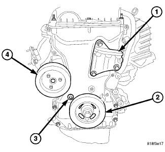
- Remove crankshaft damper (2). Refer to DAMPER, VIBRATION, REMOVAL .
- Remove three bolts and water pump pulley (4) from water pump.
- Remove lower bolt from right side engine mount bracket (1).
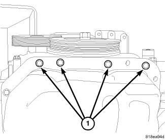
- Remove timing chain cover lower bolts (1).
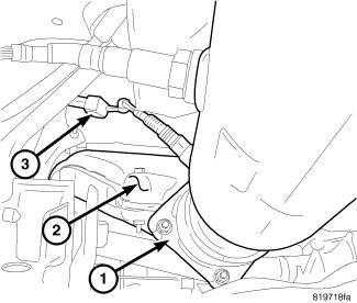
- Remove under floor catalytic converter. Refer to CONVERTER, CATALYTIC, REMOVAL .
- Lower vehicle.
- Support engine with suitable jack.
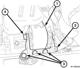
- Remove right engine mount through bolt (4).
- Remove right engine mount to mount bracket bolts (3).
- Remove right engine mount adapter (1).
- Remove accessory drive upper idler pulley (1).
- Remove right upper engine mount bracket (1).
- Remove accessory drive belt tensioner.
- Remove upper timing chain cover retaining bolts.
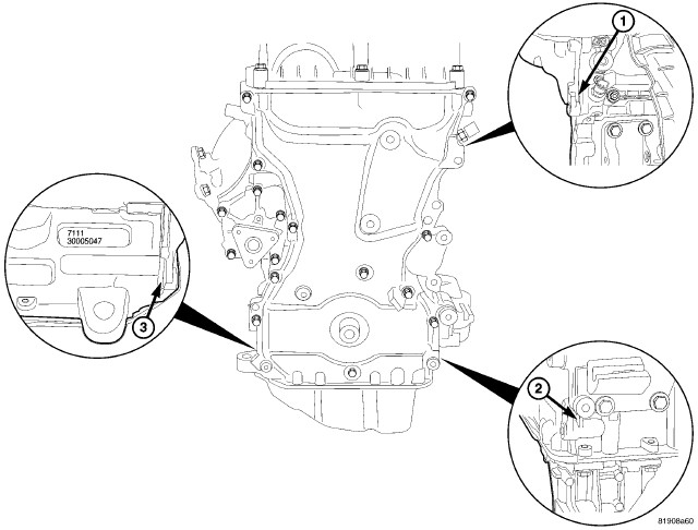
- Remove timing chain cover using pry points (1, 2, 3).
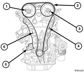
- Remove tensioner (5) and timing chain (2). Refer to CHAIN AND SPROCKETS, TIMING, REMOVAL .
- Remove timing chain guide (4) and timing chain pivot guide (6).
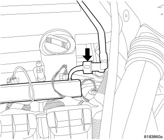
- Disconnect the fuel line from the fuel rail. Refer to FITTING, QUICK CONNECT .
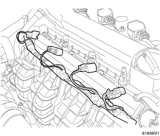
- Unlock and disconnect the electrical connectors from the fuel injectors.
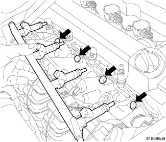
- Remove two fuel rail retaining bolts and remove fuel rail.
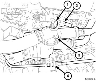
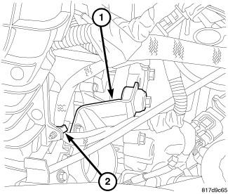
- Disconnect electrical connectors from coolant temperature sensor (1), oil temperature sensor, variable valve timing solenoids, camshaft position sensors, MAP sensor, manifold tuning valve, ignition interference suppressor (2) and electronic throttle control.
- Remove wiring harness retainer from intake manifold (2) and reposition harness.
- Remove throttle body support bracket (1).
- Disconnect vacuum lines at intake.
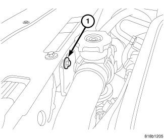
- Remove upper radiator hose retaining bolt (1).
- Remove intake manifold retaining bolts and remove intake manifold.
- Remove four bolts and reposition coolant adapter (3).
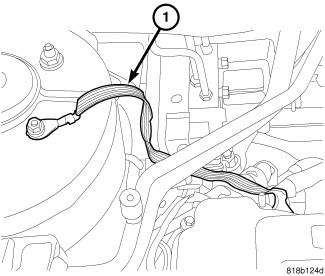
- Remove ground strap (1) at right rear of cylinder head if equipped.
NOTE:
Camshaft bearing caps should have been marked during engine manufacturing. For example, number one exhaust camshaft bearing is marked "E1>".
CAUTION:DO NOT use a number stamp or a punch to mark camshaft bearing caps. Damage to bearing caps could occur.
- Using a permanent ink or paint marker, identify location and position on each camshaft bearing cap.
- Remove the front camshaft bearing cap.
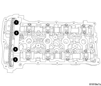
- Slowly remove the remaining intake and exhaust camshaft bearing cap bolts one turn at a time.
- Remove the camshafts.
NOTE:
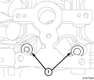
All of the cylinder head bolts have captured washers EXCEPT the front two (1).
- Remove cylinder head bolts and two uncaptured washers.
- Remove cylinder head from engine block.
- Inspect and clean cylinder head and block sealing surfaces. Refer to CLEANING and INSPECTION .


NOTE:
Ensure cylinder head bolt holes in the block are clean, dry (free of residual oil or coolant), and threads are not damaged.