Cylinder Head: Installation: Installation
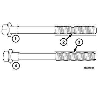
The cylinder head bolts are tightened using a torque plus angle procedure. The bolts must be examined BEFORE reuse. If the threads are necked down the bolts must be replaced.
- Check cylinder head bolts for necking by holding a scale or straight edge against the threads. If all the threads do not contact the scale (2) the bolt must be replaced.
NOTE:
Ensure cylinder head bolt holes in the block are clean, dry (free of residual oil or coolant), and threads are not damaged.
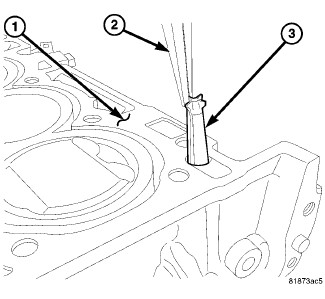
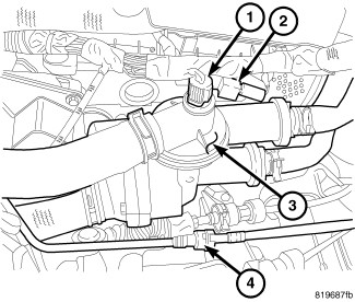
CAUTION:Always replace the variable valve timing filter screen (3) when servicing the head gasket or engine damage could result.
- Replace the variable valve timing filter screen (3).
NOTE:
When using RTV, the sealing surfaces must be clean and free from grease and oil.
NOTE:When using RTV, parts should be assembled in 10 minutes and tighten to final torque within 45 minutes.
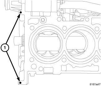
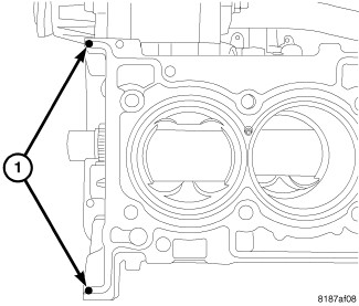
- Place two pea size dots of Mopar® engine sealant RTV or equivalent (1) on cylinder block as shown in illustration.
- Position the new cylinder head gasket on engine block with the part number facing up. Ensure gasket is seated over the locating dowels in block.
- Place two pea size dots of Mopar® engine sealant RTV or equivalent (1) on cylinder head gasket as shown in illustration.NOTE:
The head must be installed within 15 minutes before the RTV skins.
- Position cylinder head onto engine block.
CAUTION:
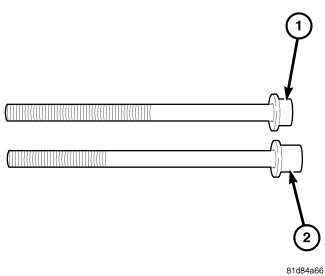
This engine was built with 2 different style cylinder head bolts. Each style bolt requires a different torque value. The bolts can be identified by the short bolt head (1) and the long bolt head (2).
- Measure the bolt head from the washer to the top of the bolt head. The short bolt head (1) measures 8 mm (5/16") and the long bolt head (2) measures 13 mm (1/2").
- Identify whether your engine has the short head design (1) or the long head design (2).
 Courtesy of CHRYSLER GROUP, LLCNOTE:
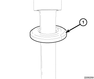
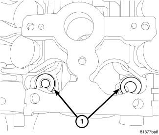
The front two cylinder head bolts do not have captured washers. The washers must be installed with the bevel edge (1) up towards the bolt head.
- Install washers (1) for the front two cylinder head bolts with the beveled edge facing up.
NOTE:
Before installing the cylinder head bolts, lubricate the threads with clean engine oil.
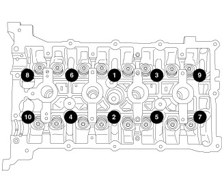
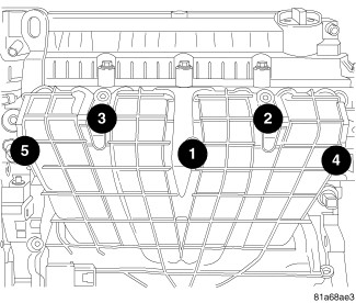
- Install the cylinder head bolts and tighten in the sequence shown in illustration.
- If your bolt has the short head (1), use the following torque specifications:
- First: All to 30 N.m (25 ft. lbs.)
- Second: All to 61 N.m (45 ft. lbs.)
- Third: All to 61 N.m (45 ft. lbs.)
- Fourth: All an additional 90°CAUTION:
Do not use a torque wrench for the Fourth step.
- If your bolt has the long head (2), use the following torque specifications:
- First: All to 30 N.m (25 ft. lbs.)
- Second: All to 73 N.m (54 ft. lbs.)
- Third: All to 73 N.m (54 ft. lbs.)
- Fourth: All an additional 90°CAUTION:
Do not use a torque wrench for the Fourth step.
- Clean excess RTV from the timing chain cover sealing surface.
- Install coolant adapter (3) with new seals. Tighten bolts to 18.1 N.m (159 in. lbs.).
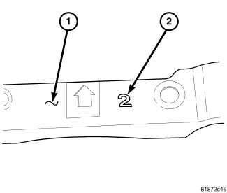
- The front camshaft bearing cap (1) is numbered (2) either one, two, or three, this corresponds to the select fit front exhaust camshaft bearing to use.
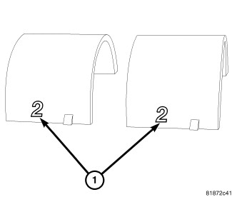
- Install the corresponding select fit front exhaust camshaft bearing (1).
- Oil all of the camshaft journals with clean engine oil.
- Position exhaust camshaft (1) and intake camshaft (2) on bearing journals in the cylinder head.
- Align camshaft timing marks (3) so that they are facing each other and are in line with the cylinder head cover sealing surface.CAUTION:
Install the front intake and exhaust camshaft bearing cap last. Ensure that the dowels are seated and follow torque sequence or damage to engine could result.
NOTE:If the front camshaft bearing cap is broken, the cylinder head MUST be replaced.
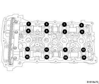
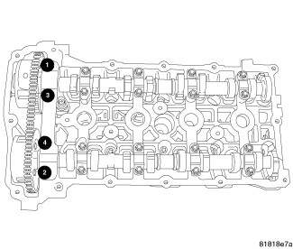
- Install intake and exhaust camshaft bearing caps and slowly tighten bolts to 9.5 N.m (85 in. lbs.) in the sequence shown in illustration.NOTE:
Verify that the exhaust bearing shells are correctly installed, and the dowels are seated in the head, prior to torquing bolts.
NOTE:This torque sequence is for vehicles with the round hole for the Front Cam Cap Dowel located on the intake side of the cylinder head.
- Install the front intake and exhaust bearing cap and tighten bolts to 25 N.m (18 ft. lbs.) in the sequence shown in illustration.
NOTE:
This torque sequence is for vehicles with the round hole for the Front Cam Cap Dowel located on the exhaust side of the cylinder head.
- Install the front intake and exhaust bearing cap and tighten bolts to 25 N.m (18 ft. lbs.) in the sequence shown in illustration.
- Install timing chain guide (4) and tighten bolts to 12 N.m (105 in. lbs.).
- Install the moveable timing chain pivot guide (6) and tighten bolt to 12 N.m (105 in. lbs.).
- Install timing chain (2) and tensioner (5). Refer to CHAIN AND SPROCKETS, TIMING, INSTALLATION .
- Install timing chain cover, engine mount, pulleys and accessory drive belt. Refer to COVER(S), ENGINE TIMING, INSTALLATION .
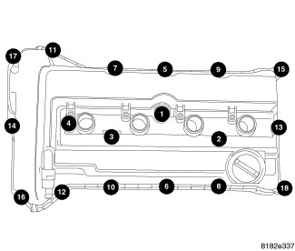
- Install cylinder head cover and ignition coils. Refer to COVER(S), CYLINDER HEAD, INSTALLATION .
- Install exhaust manifold. Refer to MANIFOLD, EXHAUST, INSTALLATION .
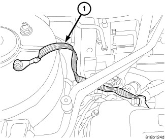
- Install ground strap (1) at right rear of cylinder head if equipped.
- Install intake manifold, vacuum lines and fuel rail. Refer to MANIFOLD, INTAKE, INSTALLATION .
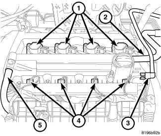
- Connect coil (1) and injector (4) electrical connectors.
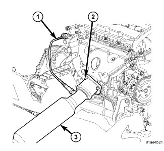
- Connect electrical connectors to coolant temperature sensor (1), camshaft position sensors, oil temperature sensor, variable valve timing solenoids, MAP sensor, manifold tuning valve, ignition interference suppressor (2) and electronic throttle control.
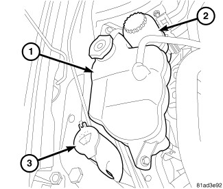
- Install power steering pump reservoir (2). Tighten mounting screw to 12 N.m (106 in. lbs.).
- Install coolant recovery reservoir (1). Tighten mounting bolts to 10 N.m (89 in. lbs.).
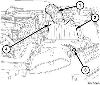
- Install clean air hose (1) and air cleaner housing (2). Refer to BODY, AIR CLEANER, INSTALLATION .
- Fill cooling system. Refer to STANDARD PROCEDURE .
- Install new oil filter and fill engine with oil.
- Connect negative battery cable.
- Operate engine until it reaches normal operating temperature. Check oil and cooling systems for leaks and correct fluid levels.
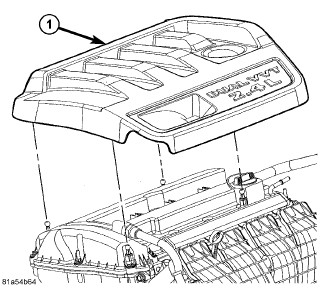
- Install engine cover (1).



The Cam/Crank Variation Relearn procedure must be performed using the scan tool anytime there has been a repair/replacement made to a powertrain system, for example: flywheel, valvetrain, camshaft and/or crankshaft sensors or components. Refer to STANDARD PROCEDURE .