Camshaft, Engine: Installation: Installation
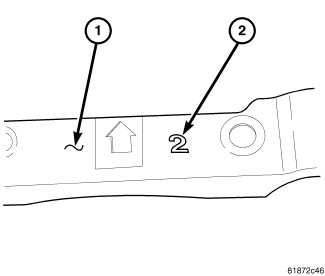
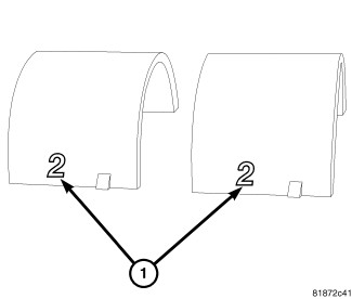
- The front camshaft bearing cap (1) is numbered (2) either one, two, or three, this corresponds to the select fit front exhaust camshaft bearing to use.
- Install the corresponding select fit front exhaust camshaft bearing (1).
- Oil all of the camshaft journals with clean engine oil.
- Install camshaft phasers on camshafts if removed. Refer to ASSEMBLY, VARIABLE VALVE TIMING, INSTALLATION .
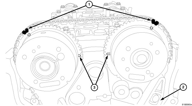
- Install timing chain onto exhaust cam sprocket making sure that the timing marks (1) on the sprocket and the painted chain link are aligned.
- Position exhaust camshaft and on bearing journals in the cylinder head.
- Align exhaust cam timing mark (3) so it is in line with the cylinder head cover sealing surface (2).
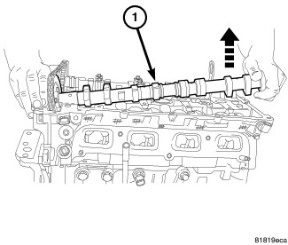
- Install intake camshaft by raising the rear of the camshaft upward and roll the sprocket into the chain.
- Align the timing marks (1) on the intake cam sprocket with the painted chain link.
- Position the intake camshaft into the bearing journals in the cylinder head.
- Verify that the timing marks (1) are aligned on both camshafts and that the timing marks (3) are facing each other and are in line with the cylinder head cover sealing surface (2).CAUTION:
Install the front intake and exhaust camshaft bearing cap last. Ensure that the dowels are seated and follow torque sequence or damage to engine could result.
NOTE:If the front camshaft bearing cap is broken, the cylinder head MUST be replaced.
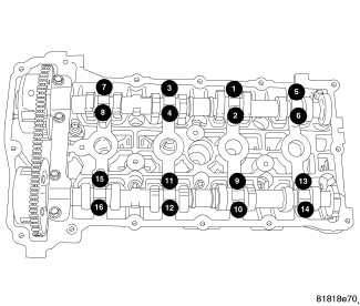
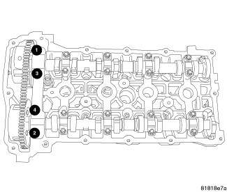
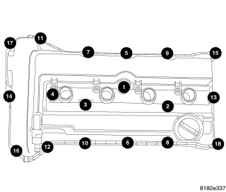
- Install intake and exhaust camshaft bearing caps and slowly tighten bolts to 9.5 N.m (85 in. lbs.) in the sequence shown in illustration.NOTE:
Verify that the exhaust bearing shells are correctly installed, and the dowels are seated in the head, prior to torquing bolts.
NOTE:This torque sequence is for vehicles with the round hole for the Front Cam Cap Dowel located on the intake side of the cylinder head.
- Install the front intake and exhaust bearing cap and tighten bolts to 25 N.m (18 ft. lbs.) in the sequence shown in illustration.
NOTE:
This torque sequence is for vehicles with the round hole for the Front Cam Cap Dowel located on the exhaust side of the cylinder head.
- Install the front intake and exhaust bearing cap and tighten bolts to 25 N.m (18 ft. lbs.) in the sequence shown in illustration.
- Verify that all timing marks (1, 3) are aligned.
- Remove Allen wrench from timing chain tensioner.
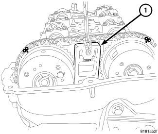
- Remove Locking Wedge (special tool #9701, Wedge, Locking) (1) by pulling straight upward on pull rope.
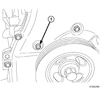
- Apply Mopar® thread sealant to timing tensioner plug (1) and Install.
- Rotate the crankshaft CLOCKWISE two complete revolutions until the crankshaft is repositioned at the TDC position.
- Verify that the camshafts timing marks (3) are in the proper position and in line with the cylinder head cover sealing surface. If the marks do not line up, the timing chain is not correctly installed.
- Install right splash shield. Refer to SHIELD, SPLASH, FRONT WHEELHOUSE, INSTALLATION .
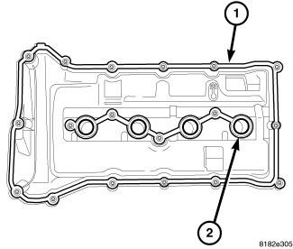
- Remove RTV from gasket (1).
- Inspect cylinder head cover gaskets (1, 2) for damage. If no damage is present, gaskets can be re-installed.
- Install cylinder head cover . Refer to COVER(S), CYLINDER HEAD, INSTALLATION .
- Connect negative battery cable.
- Fill cooling system. Refer to STANDARD PROCEDURE .
- Fill with oil.
- Operate engine until it reaches normal operating temperature. Check oil and cooling systems for correct fluid levels.
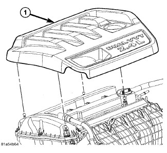
- Install engine cover (1).



The Cam/Crank Variation Relearn procedure must be performed using the scan tool anytime there has been a repair/replacement made to a powertrain system, for example: flywheel, valvetrain, camshaft and/or crankshaft sensors or components. Refer to STANDARD PROCEDURE .