Engine Block: Crankshaft: Removal: Removal
WARNING: This page is about a different variant/trim than selected.
NOTE:
Crankshaft can not be removed when engine is in vehicle.
- Remove engine assembly from vehicle. Refer to REMOVAL .
- Separate transaxle from engine.
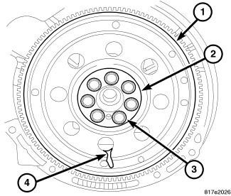
- Remove flex plate/flywheel (1).
- Remove crankshaft rear oil seal. Refer to SEAL, CRANKSHAFT OIL, REAR, REMOVAL .
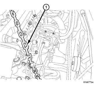
- Remove engine from lift chain (1) and mount engine on a suitable repair stand.
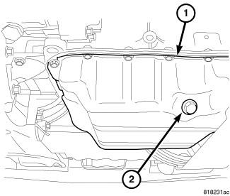
- Drain engine oil (2).
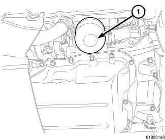
- Remove oil filter (1).
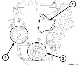
- Remove crankshaft vibration damper (2). Refer to DAMPER, VIBRATION, REMOVAL .
- Remove water pump pulley (3).
- Remove engine mount support bracket (1).
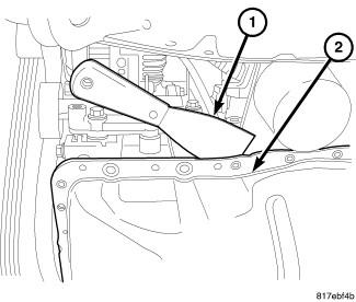
- Remove the oil pan (2). Refer to PAN, OIL, REMOVAL .
- Remove timing chain cover . Refer to COVER(S), ENGINE TIMING, REMOVAL .
- Remove the timing chain. Refer to CHAIN AND SPROCKETS, TIMING, REMOVAL .
- Remove balance shaft module.
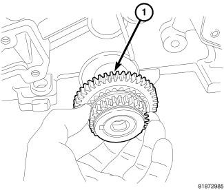
- Remove the crankshaft sprocket (1).
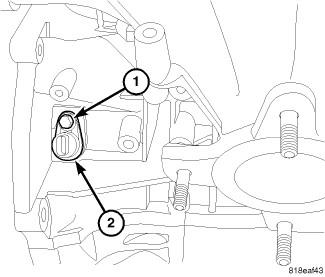
- Remove crankshaft position sensor retaining bolt (1) and remove sensor (2).
- Remove ladder frame. Refer to
FRAME, LADDER, REMOVAL .
NOTE:
If piston/connecting rod replacement is necessary, remove cylinder head. Refer to CYLINDER HEAD, REMOVAL .
CAUTION:DO NOT use a number stamp or a punch to mark connecting rods. Damage to connecting rod could occur.
- Using a permanent ink or paint marker, identify cylinder number on each connecting rod and cap.
- Remove all connecting rod bolts and caps. Care should be taken not to damage the fracture rod and cap surfaces.
NOTE:
Do not reuse connecting rod bolts.
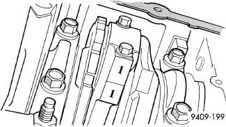
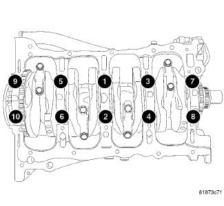
- Remove main bearing caps.CAUTION:
Use extreme care when handling crankshaft. Tone wheel damage can occur if crankshaft is mis-handled.
- Lift out crankshaft from cylinder block. Do not damage the main bearings or journals when removing the crankshaft.