Pump, Engine Oil: Installation: Installation
WARNING: This page is about a different variant/trim than selected.
multimedia:A supplement to the article is available.
CAUTION:
There are two different Balance Shaft Module (BSM) to engine block bolts used. 180 mm bolts with a lock-patch on the threads or 185 mm bolts without lock-patch. Do not reuse the 180 mm bolts. Always discard 180 mm bolts after removing. Failure to replace these bolts can result in engine damage. The 185 mm bolts are reusable. Install the same length bolts that were removed and use either four new 180 mm bolts or four 185 mm bolts.
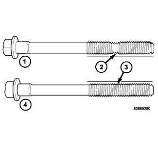
- The 185 mm (7.283 in.) length bolts must be checked for stretching. Check the bolts with a straight edge for necking (2). If the bolts are necked down, they must be replaced.
- Clean the balance shaft/oil pump assembly mounting holes with Mopar® brake parts cleaner.
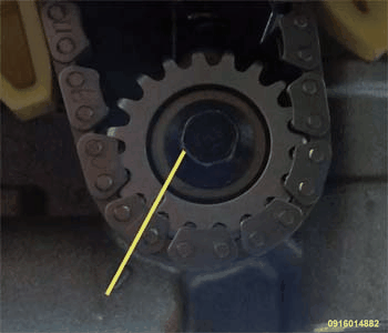
- Align the marks on the balance shaft/oil pump assembly and drive sprocket.
- With the rear of the balance shaft/oil pump assembly on a slight downward angle, position the gear into the chain links. Make sure the paint marks are aligned.
- Pivot balance shaft/oil pump assembly upwards and position on ladder frame.
- Start balance shaft/oil pump assembly mounting bolts by hand.NOTE:
Use a three step procedure when tightening balance shaft/oil pump assembly mounting bolts. For new 180 mm bolts, go to step 7. For 185 mm bolts, go to step 8 .
- Tighten new 180 mm balance shaft/oil pump assembly mounting bolts as follows:
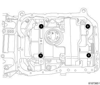
- Tighten to 15 N.m (11 ft. lbs.) in the sequence shown in illustration.
- Tighten to 33 N.m (24 ft. lbs.) in the sequence shown in illustration.
- Rotate bolts an additional 90° in the sequence shown in illustration.
- Tighten 185 mm balance shaft/oil pump assembly mounting bolts as follows:
- Tighten to 15 N.m (11 ft. lbs.) in the sequence shown in illustration.
- Tighten to 29 N.m (22 ft. lbs.) in the sequence shown in illustration.
- Rotate bolts an additional 90° in the sequence shown in illustration.
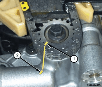
- Double check the alignment marks to ensure the gear (1) and balance shaft/oil pump assembly indicator (2) is aligned.
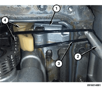
- Remove the tie strap (3).
- Remove the bracket bolt (2).
- Inspect that the tensioner (1) has fully extended and applied pressure to the guide and chain (4).
- Install the oil pan
Refer to PAN, OIL, INSTALLATION .
- Fill engine with oil.
- Start engine and check for leaks.