Removal - MANIVERTER (AWD)
WARNING: This page is about a different variant/trim than selected.
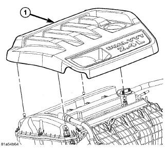
- Remove the engine cover (1).
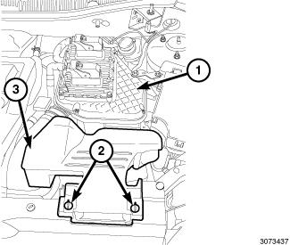
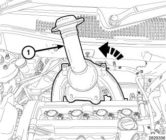
- Unlock the retainers (2) and remove the fresh air inlet duct (3) from air cleaner body (1).
- Disconnect and isolate the negative battery cable.
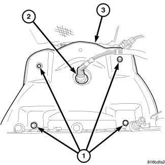
- Remove the upstream oxygen sensor (2). Refer to SENSOR, OXYGEN, REMOVAL .
- Remove the upper heat shield attaching bolts (1) and the upper heat shield (3).
- Raise and support the vehicle. Refer to HOISTING, STANDARD PROCEDURE .
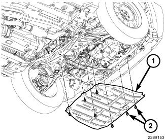
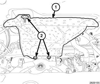
- If equipped, remove seven bolts (2) and the front skid plate (1).
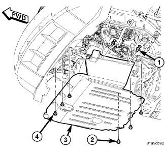
- If equipped, remove the side push pin fasteners (1), three rear screws (2), three front screws (4) and the belly pan (3).
- Partially drain the cooling system. Refer to STANDARD PROCEDURE .
- Disconnect the wire harness connector from the downstream oxygen sensor (2).
- Remove the exhaust pipe to maniverter bolts (1) and reposition the exhaust pipe.
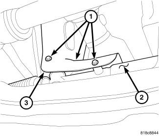
- Remove three bolts (1) and the steering gear heat shield (3).
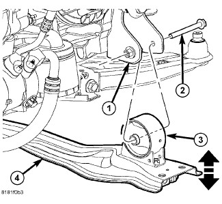
- Remove the front engine mount bolt (2) and the front fore and aft crossmember (4). Refer to CROSSMEMBER, FRONT FORE AND AFT, REMOVAL .
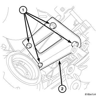
- Remove the four bolts (1) and the maniverter support bracket (2).
- Remove exhaust maniverter lower retaining fasteners.
- Lower the vehicle.
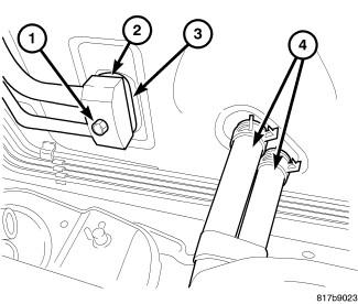
- Remove the heater hoses (4) and installed plugs or caps to the heater core tubes.
- Remove three speed-nuts (2) and the dash panel heatshield (1).
- Remove the upper exhaust maniverter retaining fasteners and reposition the maniverter.NOTE:
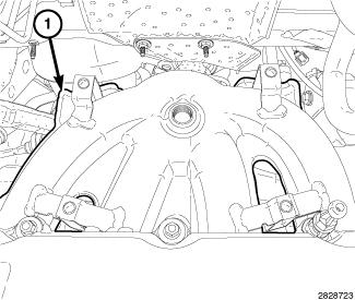
The lower maniverter heatshield (1) must be removed from the maniverter before the maniverter is removed from the vehicle.
- Remove the lower heat shield (1) from the maniverter.
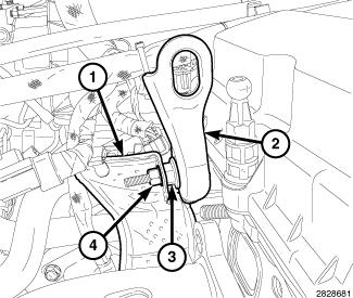
- Remove the nut (4) and repositioned the heatshield (1).
- Remove the stud bolt (3) and the engine lift bracket (2).
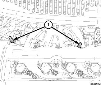
- Remove two engine cover mounting posts (1).
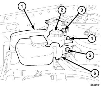
- Remove the bolt (5) and reposition the engine coolant reservoir (6).
- Remove the bolt (4) and reposition the power steering fluid reservoir (2).
- Remove the bolt (3) and reposition the washer fluid reservoir (1).
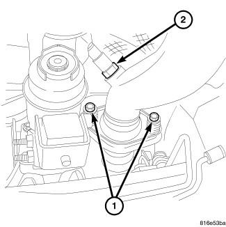
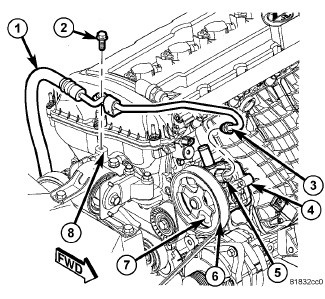
- Remove the bolt (2) from the power steering pressure hose support bracket.
- Support the engine with a block of wood on a suitable jack.
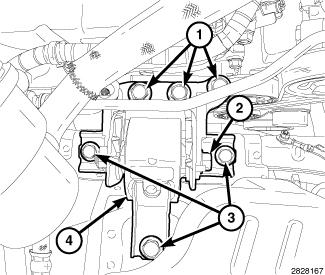
- Remove the engine mount isolator retaining bolts (3).
- Remove the engine mount bracket retaining bolts (1) and remove the right engine mount (4).
- Adjust the jack to lower the engine.
- Rotate the maniverter (1) counterclockwise 180° and remove it from above/between the engine and dash panel.
- Remove and discard the maniverter gasket.