Installation - MANIVERTER (AWD)
WARNING: This page is about a different variant/trim than selected.
- Install a new maniverter gasket on the cylinder head. DO NOT APPLY SEALER .
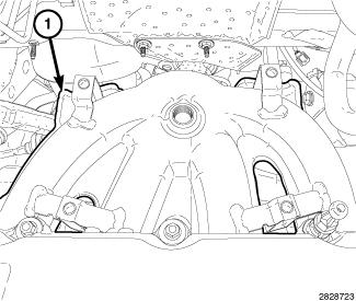
- Position the maniverter (1) in the engine compartment as shown in illustration. Rotate the maniverter 180° clockwise into position.
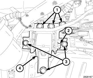
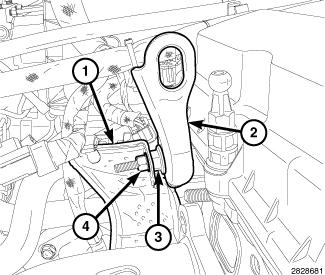
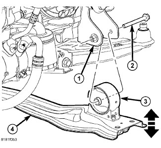
- Raise the engine and position the right engine mount (4) in place.
- Install the engine mount bracket retaining bolts (1) and tighten to 68 N.m (50 ft. lbs.).
- Install engine mount isolator retaining bolts (3) and tighten to 75 N.m (55 ft. lbs.).
- If removed, install the engine mount through bolt (2) and tighten to 88 N.m (65 ft. lbs.).
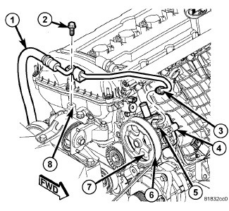
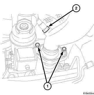
- Install the power steering pressure hose support bracket to the engine mount bracket (8) with the bolt (2) tightened to 18 N.m (14 ft. lbs.).
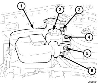
- Install the washer fluid reservoir (1) with the bolt (3) tightened to 9 N.m (79 in. lbs.).
- Install the power steering fluid reservoir (2) with the bolt (4) tightened to 12 N.m (106 in. lbs.).
- Install the engine coolant reservoir (6) with the bolt (5) tightened to 4 N.m (35 in. lbs.).
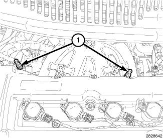
- Install two engine cover mounting posts (1) and tighten to 4 N.m (35 in. lbs.).
- Install the engine lift bracket (2) with the stud bolt (3) tightened to 25 N.m (18 ft. lbs.).
- Install the repositioned heatshield (1) to the stud bolt (3) with the nut (4) tightened to 9 N.m (79 in. lbs.).
NOTE:
The lower maniverter heatshield (1) must be placed in position before the maniverter is installed to the cylinder head.
- Position the lower heat shield (1) in its installed position on the maniverter.
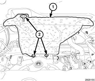
- Install the dash panel heatshield (1) with three speed-nuts (2) tightened to 1 N.m (10 in. lbs.).
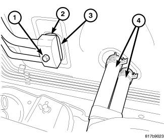
- Remove the previously installed plugs or caps and connect the heater hoses (4) to the heater core tubes.
- Raise and support the vehicle. Refer to HOISTING, STANDARD PROCEDURE .
- Tighten the maniverter to cylinder head fasteners, starting at the center and progressing outward in both directions to 34 N.m (300 in. lbs.). Raise and lower the vehicle for fastener access as necessary.
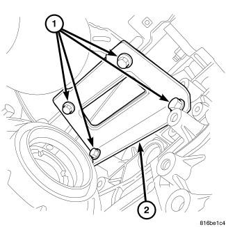
- Install the maniverter support bracket (2) with four bolts (1) tightened to 25 N.m (18 ft. lbs.).
- Install the front fore and aft crossmember (4) and front engine mount bolt (2). Refer to CROSSMEMBER, FRONT FORE AND AFT, INSTALLATION .
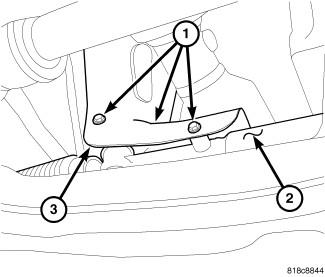
- Install the steering gear heat shield (3) with three bolts (1) tightened to 8 N.m (71 in. lbs.).
- Install the exhaust pipe to maniverter bolts (1) and tighten to 28 N.m (250 in. lbs.).
- Connect the wire harness connector to the downstream oxygen sensor (2).
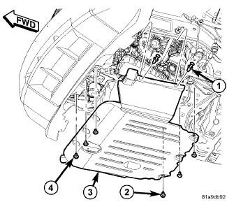
- If removed, install the belly pan (3) with three front screws (4), three rear screws (2) and side push pin fasteners (1).
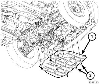
- If removed, install the front skid plate (1) with seven bolts (2) tightened to 30 N.m (22 ft. lbs.).
- Lower the vehicle.
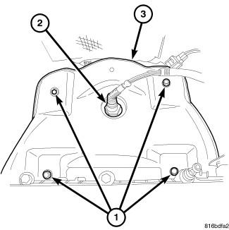
- Install the maniverter heat shields (3) with four bolts (1) tightened to 12 N.m (106 in. lbs.).
- Install the upstream oxygen sensor (2) and connect the electrical connector. Refer to SENSOR, OXYGEN, INSTALLATION .
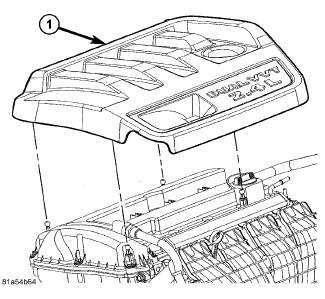
- Install the engine cover (1).
- Connect the negative battery cable and tighten nut to 5 N.m (45 in. lbs.).
- Install the fresh air inlet duct (3) on the air cleaner body (1) and lock the retainers (2).
- Fill the cooling system. Refer to STANDARD PROCEDURE .
- Run the engine until it reaches normal operating temperature. Check cooling system for correct fluid level. Refer to STANDARD PROCEDURE .