Manifold, Intake: Removal: Removal
WARNING: This page is about a different variant/trim than selected.
WARNING:
Release fuel system pressure before servicing system components. Service vehicles in well ventilated areas and avoid ignition sources. Never smoke while servicing the vehicle.
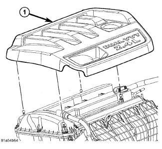
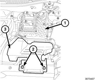
- Remove the engine cover (1).
- Perform the fuel system pressure release procedure before attempting any repairs. Refer to FUEL SYSTEM PRESSURE RELEASE PROCEDURE .
- Unlock the retainers (2) and remove the fresh air inlet duct (3) from air cleaner body (1).
- Disconnect and isolate the negative battery cable.
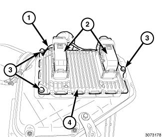
- Unlock and disconnect the electrical connectors (2) from the PCM (4).
- Remove the mounting bolt (3) and ground wire (1).
- Remove the air inlet tube (2) from the air cleaner body (1).
- Disconnect the make-up air hose (3) from the air cleaner body.
- Remove the support bracket bolt from the strut tower.
- Pull upward to disengage the pins from the rubber grommets and remove the air cleaner body (1).
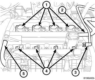
- Disconnect the fuel line (3) from the fuel rail. Refer to FITTING, QUICK CONNECT .
- Remove fuel injector electrical connectors (4).
- Remove fuel rail retaining bolts and remove fuel rail.
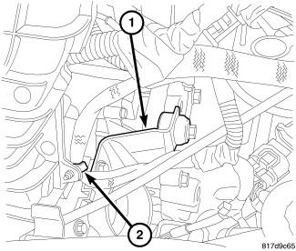
- Disconnect the oil temperature sensor (1).
- Disconnect the variable valve timing solenoid electrical connector.
- Disconnect the intake camshaft position sensor electrical connector.
- Position the harness out of the way.
- Remove the throttle body support bracket (1).
- Disconnect the electronic throttle control electrical connector.
- Remove the wiring harness retainer from the intake manifold (2).
- Disconnect the MAP sensor electrical connector.
- Disconnect the vacuum lines from the intake manifold.
- Remove the upper radiator hose retaining bracket (1).
- Remove intake manifold retaining bolts.
- Remove intake manifold.