Diagnosis And Testing - Transmission Range Sensor (TRS)
The TRS is monitored by the Transmission Control Module (TCM). A diagnostic scan tool can be used to monitor various outputs of the TRS as well to display any Diagnostic Trouble Codes (DTC). If any DTCs are encountered refer to the appropriate diagnostic test procedure. Refer to the DTC INDEX article. .
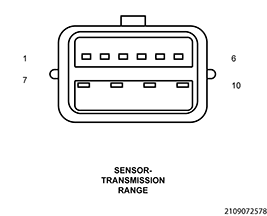
The TRS can be tested for functionality by measuring continuity between the pins indicated in the chart for each gear position. Pin 7 and pin 10 are used for Park and Neutral safety function of the starter motor circuit.
| TRS CONTINUITY | ||||||||
|---|---|---|---|---|---|---|---|---|
| PIN 1 (T1) |
PIN 2 (T42) |
PIN 3 (T16) |
PIN 5 (T3) |
PIN 7 (Z921) |
PIN 8 (T4) |
PIN 9 (T42) |
PIN 10 (T120) |
|
| PARK / NEUTRAL (Park / Neutral Safety) |
X | X | ||||||
| PARK | X | X | ||||||
| REVERSE | X | X | ||||||
| NEUTRAL | X | X | ||||||
| DRIVE | X | X | ||||||
| LOW | X | X | ||||||