Valve Body: Removal: Removal
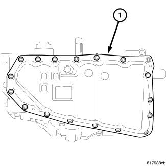
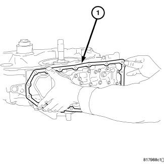
- Remove the bolts holding the oil pan (1) to the transaxle case.
- Remove the oil pan from the transaxle case.
- Remove the oil pan gasket (1) from the transaxle case.
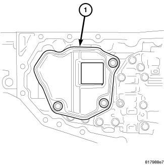
- Remove the bolts holding the oil strainer (1) to the valve body.
- Remove the oil strainer.
- Remove and discard the oil strainer o-ring.
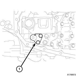
- Remove the bolts holding the oil strainer bracket (1) to the valve body assembly.
- Remove the oil strainer bracket from the valve body assembly.
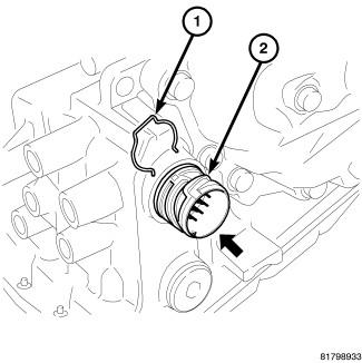
- Remove the snap ring (1) from the terminal body (2).
- Remove the nut holding the manual lever (1) to the manual shaft.
- Remove the manual lever from the manual shaft.
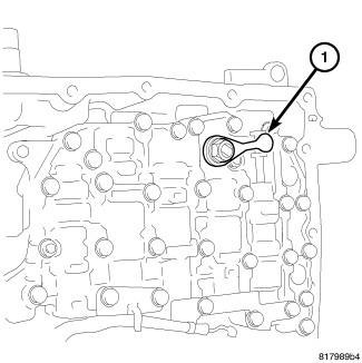
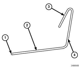
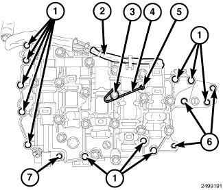
- To remove the control valve body assembly on to the transaxle case, fabricate a rod to set the pulley ratio linkage as shown in illustration. (1) 2 mm (0.08 in.) Diameter, (2) 80 mm (3 in.) long, (3) 30 mm (1 in.) long, (4) 50 mm (2 in.) long.
- Install the rod into the linkage stopper hole (5) of the control valve assembly and secure under bolt head (3).
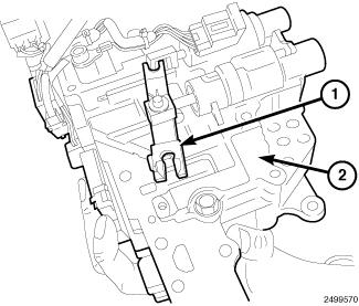
- This sets the pulley ratio linkage (1) in position on the valve body (2).CAUTION:
Tilt the valve body assembly away from the transaxle case on the manual shaft side to ease removal. Pay attention to completely remove the terminal body from the transaxle case.
 Courtesy of CHRYSLER GROUP, LLCNOTE:
Mounting bolt (7) is shorter than bolts (1).
- Remove the mounting bolts (1) and (7) of the control valve body assembly.
- Remove the valve body assembly from the transaxle case.