Diagnostic Test
- CHECK FOR DTC C100A-LEFT FRONT WHEEL SPEED SENSOR CIRCUIT NOTE:
This DTC must be active for the results of this test to be valid.
- Turn the ignition on.
- With the scan tool, record and erase DTCs.
- Cycle the ignition switch from off to on.
- With the scan tool, read DTCs.
Does the scan tool display: C100A-LEFT FRONT WHEEL SPEED SENSOR CIRCUIT active?
Yes
- Go To 2
No
- The condition that caused the symptom is currently not present. Inspect the related wiring for a possible intermittent condition. Look for any chafed, pierced, pinched, or partially broken wires.
- Perform the ABS-INTERMITTENT CONDITION TEST. Refer to ABS-INTERMITTENT CONDITION .
- CHECK CONNECTOR/TERMINAL FOR DAMAGE NOTE:
Check all terminals for broken, bent, pushed out, or corroded terminals.
- Turn the ignition off.
- Inspect the Anti-Lock Brake Module harness connector, Left Front WSS, and Left Front WSS harness connector.
Is the Left Front WSS or any of the connectors/terminals damaged?
Yes
- Repair as necessary.
- Perform ABS VERIFICATION TEST. Refer to ABS VERIFICATION TEST .
No
- Go To 3
- CHECK (B9) LEFT FRONT WSS SUPPLY CIRCUIT VOLTAGE
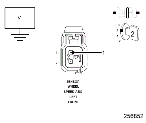 Courtesy of CHRYSLER GROUP, LLC
 - CHECK (B9) LEFT FRONT WSS SUPPLY CIRCUIT SHORT TO GROUND
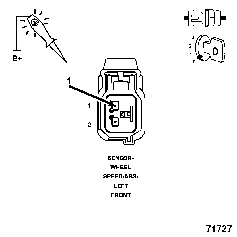 Courtesy of CHRYSLER GROUP, LLC
- Disconnect the Anti-Lock Brake Module harness connector.
- Using a 12-volt test light connected to 12-volts, probe the (B9) Left Front WSS Supply circuit.
Does the test light illuminate brightly?
Yes
- Repair the (B9) Left Front WSS Supply circuit for a short to ground.
- Perform ABS VERIFICATION TEST. Refer to ABS VERIFICATION TEST .
No
- Go To 5
- CHECK (B9) LEFT FRONT WSS SUPPLY CIRCUIT OPEN Courtesy of CHRYSLER GROUP, LLC
- Connect a jumper wire between ground and the (B9) Left Front WSS Supply circuit in the Anti-Lock Brakes Module harness connector.
- Using a 12-volt test light connected to 12-volts, probe the (B9) Left Front WSS Supply circuit.
Does the test light illuminate brightly?
Yes
- Go To 6
No
- Repair the (B9) Left Front WSS Supply circuit for an open.
- Perform ABS VERIFICATION TEST. Refer to ABS VERIFICATION TEST .
- CHECK (B8) LEFT FRONT WSS SIGNAL CIRCUIT SHORT TO VOLTAGE
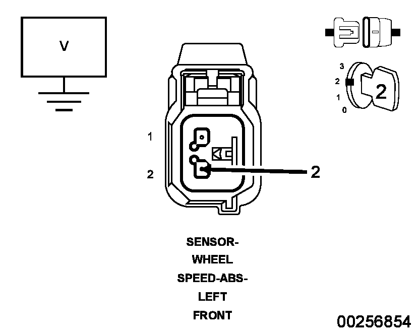 Courtesy of CHRYSLER GROUP, LLC
- Turn the ignition on.
- Measure the voltage between the (B8) Left Front WSS Signal circuit and ground.
Is the voltage above one volt?
Yes
- Repair the (B8) Left Front WSS Signal circuit for a short to voltage.
- Perform ABS VERIFICATION TEST. Refer to ABS VERIFICATION TEST .
No
- Go To 7
- CHECK (B8) LEFT FRONT WSS SIGNAL CIRCUIT SHORT TO GROUND
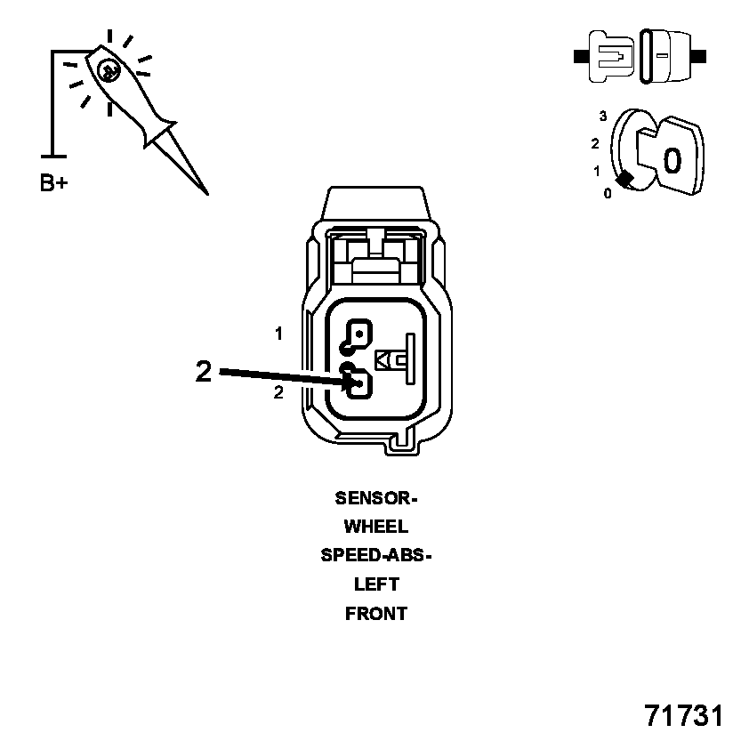 Courtesy of CHRYSLER GROUP, LLC
- Turn the ignition off.
- If not done previously, disconnect the Anti-Lock Brake Module harness connector.
- Using a 12-volt test light connected to 12-volts, probe the (B8) Left Front WSS Signal circuit.
Does the test light illuminate brightly?
Yes
- Repair the (B8) Left Front WSS Signal circuit for a short to ground.
- Perform ABS VERIFICATION TEST. Refer to ABS VERIFICATION TEST .
No
- Go To 8
- CHECK (B8) LEFT FRONT WSS SIGNAL CIRCUIT OPEN Courtesy of CHRYSLER GROUP, LLC
- Connect a jumper wire between ground and the (B8) Left Front WSS Signal circuit in the Anti-Lock Brakes Module harness connector.
- Using a 12-volt test light connected to 12-volts, probe the (B8) Left Front WSS Signal circuit.
Does the test light illuminate brightly?
Yes
- Go To 9
No
- Repair the (B8) Left Front WSS Signal circuit for an open.
- Perform ABS VERIFICATION TEST. Refer to ABS VERIFICATION TEST .
- CHECK (B8) LEFT FRONT WSS SIGNAL CIRCUIT AND (B9) LEFT FRONT WSS SUPPLY CIRCUIT SHORT TOGETHER
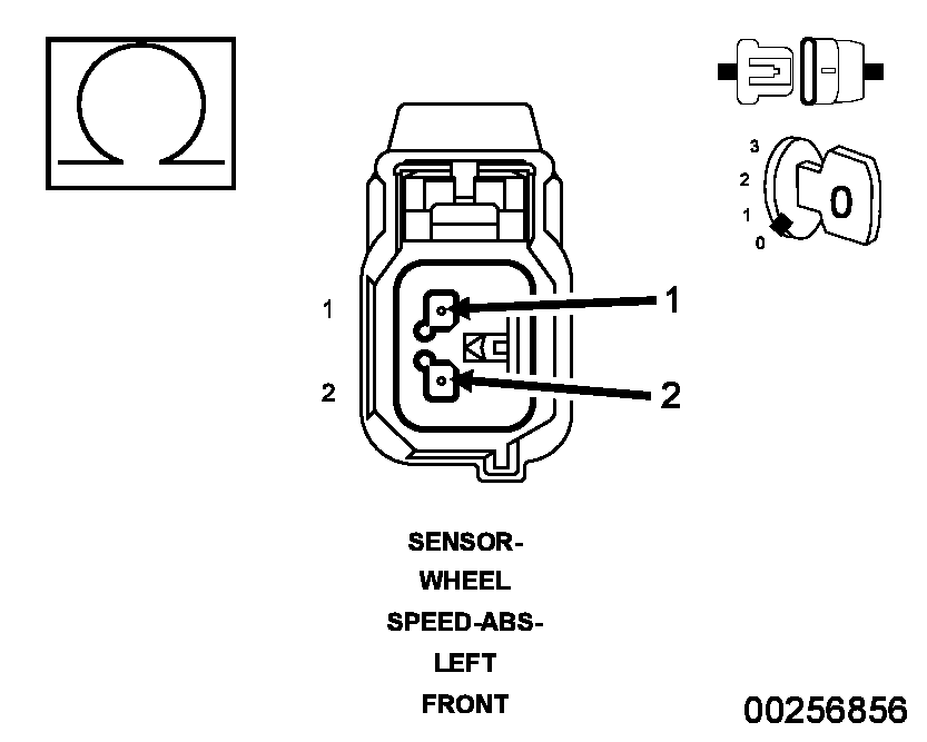 Courtesy of CHRYSLER GROUP, LLC
- Remove all jumper wires.
- Measure the resistance between the (B8) Left Front WSS Signal circuit and the (B9) Left Front WSS Supply circuit.
Is the resistance above 5.0 ohms?
Yes
- Go To 10
No
- Repair the (B8) Left Front WSS Signal circuit and the (B9) Left Front WSS Supply circuit for a short together.
- Perform ABS VERIFICATION TEST. Refer to ABS VERIFICATION TEST .
- LEFT FRONT WHEEL SPEED SENSOR
- Replace the Left Front Wheel Speed Sensor in accordance with the Service Information.
- Perform ABS VERIFICATION TEST. Refer to ABS VERIFICATION TEST .WARNING:
To avoid possible serious or fatal injury, check brake capability is available before road testing.
- Road test the vehicle over 40 km/h (25 mph).NOTE:
Vehicle must be driven above 40 km/h (25 mph) for set conditions to be met.
- With the scan tool, read ABS DTCs.
Did DTC C100A-LEFT FRONT WHEEL SPEED SENSOR CIRCUIT reset?
Yes
- Replace the Anti-Lock Brakes Module in accordance with the Service Information.
- Perform ABS VERIFICATION TEST. Refer to ABS VERIFICATION TEST .
No
- Test Complete.