Diagnostic Test
- VERIFY DTC IS ACTIVE NOTE:
Make sure the IOD fuse is installed and battery voltage is between 10 and 16 volts before proceeding.
- Turn the ignition on.
- With the scan tool, read and record the ABS DTCs.
- With the scan tool, read and record Environmental Data to help identify the conditions in which the DTC was set.
- With the scan tool, erase the ABS DTCs.
- Cycle the ignition switch.
- With the scan tool, read the ABS DTCs.
Does this DTC reset?
Yes
- Go To 2
No
- The condition that caused the symptom is currently not present. Inspect the related wiring for a possible intermittent condition. Look for any chafed, pierced, pinched, or partially broken wires.
- Perform the ABS INTERMITTENT CONDITION TEST. Refer to ABS-INTERMITTENT CONDITION .
- CHECK FOR ANY OF THE FOLLOWING ACTIVE DTCs
- With the scan tool, read all active DTCs from all CAN C Bus modules.NOTE:
Check for CAN C hardware electrical, VIN Missing/Mismatch, battery or ignition related DTCs.
Does the scan tool display any active DTCs related to the conditions listed above?
Yes
- Diagnose and repair the DTC(s). Refer to DIAGNOSTIC CODE INDEX .
No
- Go To 3
- With the scan tool, read all active DTCs from all CAN C Bus modules.
- CHECK THE VOLTAGE ON THE (F202) IGNITION SWITCH OUTPUT CIRCUIT
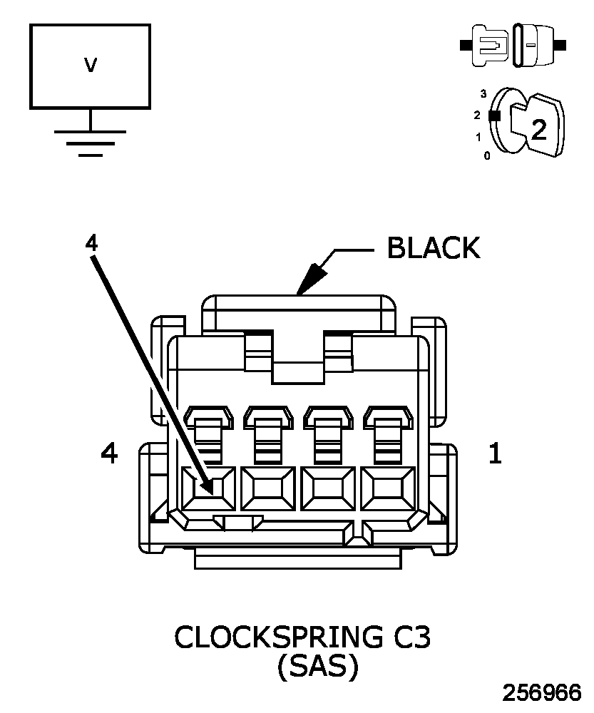 Courtesy of CHRYSLER GROUP, LLC
- Turn the ignition off.
- Disconnect the Steering Angle Sensor harness connector.
- Turn the ignition on.
- Measure the voltage of the (F202) Ignition Switch Output circuit.
Is the voltage above 10 volts?
Yes
- Go To 4
No
- Repair the (F202) Ignition Switch Output circuit for an open.
- Perform the ABS VERIFICATION TEST. Refer to ABS VERIFICATION TEST .
- CHECK THE RESISTANCE OF THE (Z937) GROUND CIRCUIT
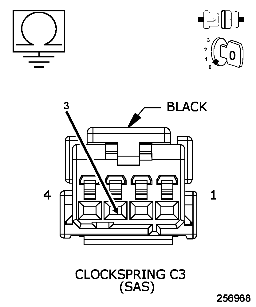 Courtesy of CHRYSLER GROUP, LLC
- Turn the ignition off.
- Measure the resistance between the (Z937) Ground circuit and ground.
Is the resistance below 5.0 Ohms?
Yes
- Go To 5
No
- Repair the (Z937) Ground circuit for an open.
- Perform the ABS VERIFICATION TEST. Refer to ABS VERIFICATION TEST .
- VERIFY THAT THE STEERING ANGLE SENSOR IS ACTIVE ON THE BUS
- With the scan tool, select ECU View.
- Verify that the Steering Angle Sensor is active on the bus.
Is the Steering Angle Sensor active on the bus?
Yes
- Replace the Steering Angle Sensor in accordance with the service information.
- Perform the ABS VERIFICATION TEST. Refer to ABS VERIFICATION TEST .
No
- Refer to STORED LOST COMMUNICATION DTCS and perform the Stored Lost Communication DTC diagnostic procedure.