Brake And Piston, 2-6: Installation: Installation
WARNING: This page is about a different variant/trim than selected.
NOTE:
Do not wash the fluid pump housing in solvent prior to assembling the 2-6 brake piston unless the fluid pump itself required an overhaul.
NOTE:
Wash the 2-6 brake piston components in suitable solvent and dry them with regulated 344 kPa (50 psi) shop air.
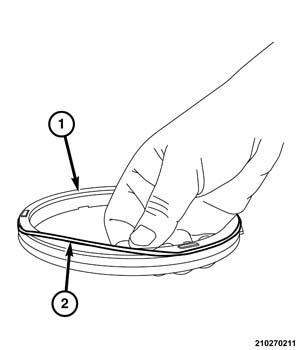
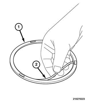
- Install the outer o-ring seal into the groove in the circumference of the 2-6 brake piston.
- Install the inner o-ring seal into the groove in the center of the 2-6 brake piston.
- Coat the 2-5 brake piston and o-ring seals with Automatic Transmission Fluid (ATF) to ease installation.
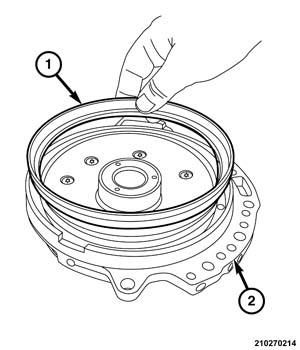
- Place the 2-6 brake piston in position in the groove in the fluid pump housing assembly.
- Push the 2-6 brake piston downward until the piston reaches the bottom of the groove in the fluid pump assembly.
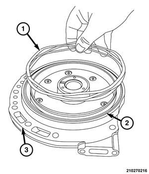
- Place the return spring into the groove in the fluid pump housing.
- Place the return spring retainer on the return spring.
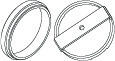
- Place Tool over the 2-6 brake piston return spring retainer.
(special tool #10427, Compressor, Return Spring)
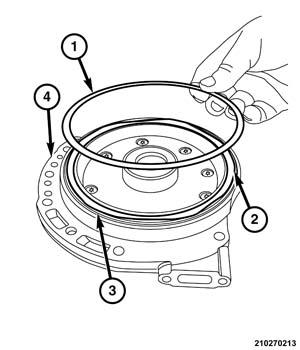
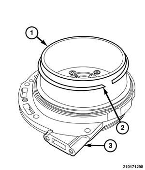
- Position the snap-ring over the circumference of the Tool guide.
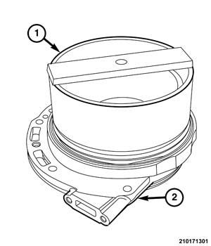
- Position Tool Installer over the snap-ring.
(special tool #10427, Compressor, Return Spring)
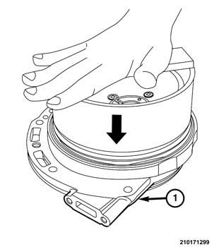
- Push the installer downward until the snap-ring locks in the groove in the fluid pump hub.
- Remove the tools from the fluid pump.
- Install the fluid pump in the transaxle.
- Assemble the transaxle to install the bell housing portion of the transaxle housing.
- Install the transaxle into the vehicle
- Road test the vehicle the validate the repair