Section 5 (T355 Manual Transmission (Service Information)): Removal: Removal
WARNING: This page is about a different variant/trim than selected.
- Raise hood.
- Remove the resonator.
- Remove engine cover.
- Remove air cleaner assembly.
- Disconnect negative battery cable.
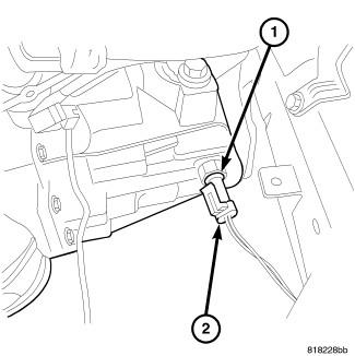
- Unplug the speed sensor connector (if equipped).
- Disconnect back-up lamp switch connector (2).
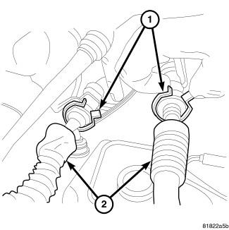
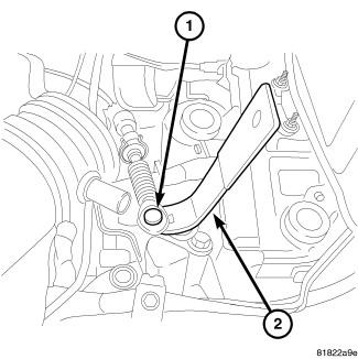
- Remove shift cable-to-bracket clips (1).
- Disconnect shift selector and crossover cable (1) from levers. Remove cables and secure out of the way.
- Remove the slave cylinder hose at bracket.
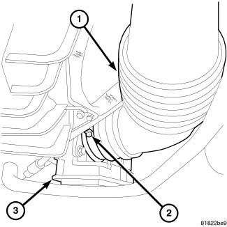
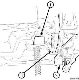
- Remove the air inlet tube (1) by loosing the screw (2) at the throttle body (3).
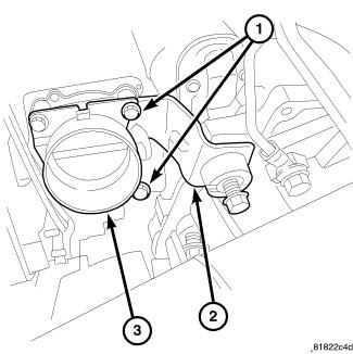
- Remove the throttle body support bracket bolts (1).
- Remove the throttle body support bracket (2).
- Remove upper bell housing bolts.
- Remove the starter bolts and slide the starter back. Refer to STARTER, REMOVAL .
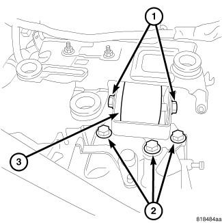
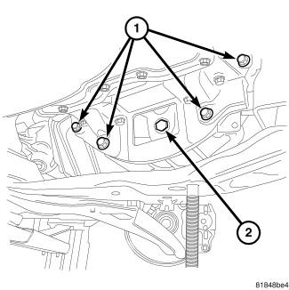
- Support transmission and loosen the left/upper transmission mount through bolt (1).
- Remove the transmission mount bolts (2).
- Raise vehicle on hoist.
- Remove the splash shields. Refer to SHIELD, SPLASH, FRONT WHEELHOUSE, REMOVAL .
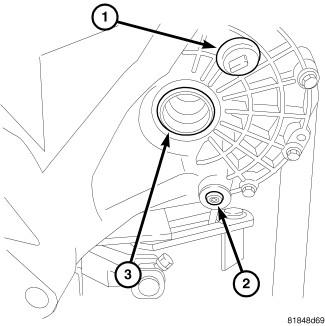
- Remove transaxle oil drain plug (2) and drain oil into a suitable container. Reinstall drain plug and tighten to 14 N.m (120 in. lbs.).
- Remove both axle halfshafts. Refer to REMOVAL .
- If equipped, remove PTU.
- Support the engine with a screw jack (1) and the transmission with a transmission jack.
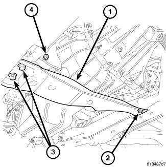
- Remove bell housing dust cover (3).
- Remove four modular clutch-to-drive plate bolts (1). While removing bolts, one tight-tolerance (slotted) drive plate hole will be encountered. When this bolt is removed, mark drive plate and modular clutch assembly at this location. Be sure to align marks upon reassembly.
- Remove the front transmission mount through bolt (4).
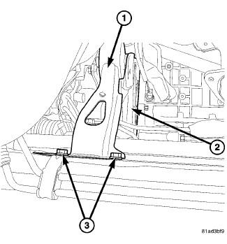
- Remove the transmission crossmember mounting bolts (2, 3).
- Remove the transmission crossmember (1).
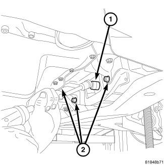
- Remove the rear transmission through bolt (4).
- Remove the rear transmission mount bolts (3) and mount (1) from the frame.
- Remove the rear transmission mount bracket bolts and bracket from transmission.
- Remove the remaining transmission bell housing bolts (1).
- Carefully lower engine and transaxle on screw jack and transmission jack until proper removal clearance is obtained.
- Obtain a helper to assist in holding transaxle while removing transaxle-to-engine mounting bolts.
- Remove transaxle from vehicle.
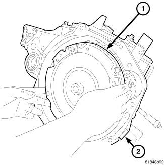
- Remove clutch module from transaxle input shaft (1).