Section 5 (T355 Manual Transmission (Service Information)): Disassembly: Disassembly
WARNING: This page is about a different variant/trim than selected.
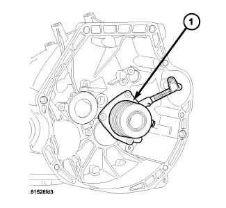
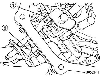
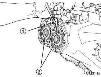
- Remove bolts from slave cylinder-to-clutch bellhousing and remove slave cylinder (1) from transaxle.
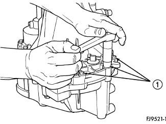
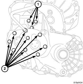
1 - CASE BOLTS The T355 transaxle internal components can be serviced only by separating the gear case from the bellhousing case.
CAUTION:The transaxle output shaft is serviced as a unit. No disassembly and reassembly is possible. Damage to the transaxle may result.
- Place transaxle on bench.
- Remove transaxle case half bolts (1).
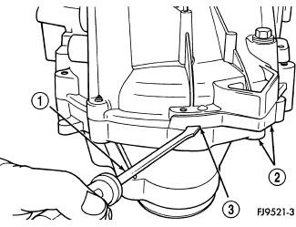
1 - PRY TOOL 2 - CASE HALVES 3 - PRY SLOT - Place two screwdrivers (1) into the slots (3) provided in the case halves (2) near the dowels. Separate the case halves.
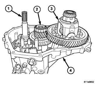
1 - INPUT SHAFT 2 - OUTPUT SHAFT 3 - DIFFERENTIAL ASSEMBLY 4 - GEARTRAIN HOUSING - Remove bellhousing half from gear case half (4).
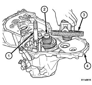
1 - INPUT SHAFT 2 - OUTPUT SHAFT 3 - DIFFERENTIAL ASSEMBLY 4 - GEARTRAIN HOUSING - Remove differential assembly (3) from housing (4).
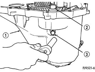
1 - CASE 2 - REVERSE IDLER SHAFT 3 - REVERSE IDLER SHAFT BOLT - Remove reverse idler shaft bolt (3).
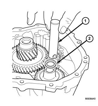
1 - REVERSE IDLER SHAFT 2 - SPACER - Remove reverse idler shaft (1).
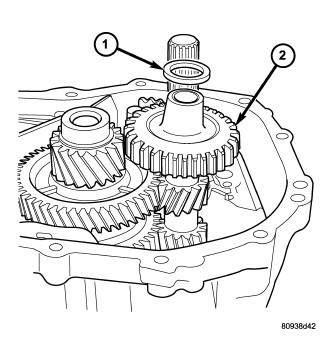
1 - SPACER 2 - REVERSE IDLER GEAR - Remove reverse idler gear (2) and spacer (1).
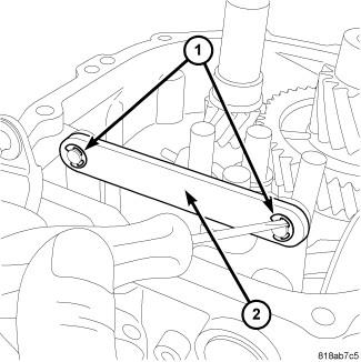
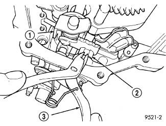
- Remove the clips (1) at the linkage tie bar (2).
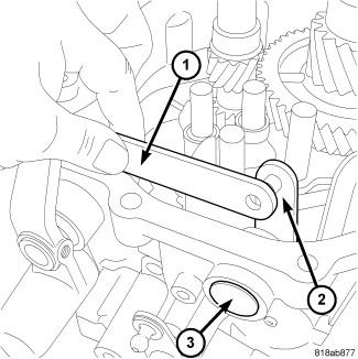
- Remove the linkage tie bar (1).
- Remove the plug (3) at the selector shaft (2).
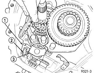
1 - SCREWS (2) 2 - REVERSE FORK BRACKET - Remove two screws (1) retaining reverse fork bracket (2).
 Courtesy of CHRYSLER GROUP, LLC
1 - REVERSE FORK BRACKET 2 - REVERSE CAM BLOCKOUT 3 - SHIFT BLOCKER ASSEMBLY - Remove reverse fork bracket (1) and reverse cam block-out assembly (2).
1 - SHIFT BLOCKER ASSEMBLY 2 - SELECTOR SHAFT SPACER (PLASTIC) 3 - SNAP RING PLIERS - Using snap-ring pliers (3), remove link shaft spacer (2).
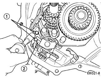
1 - SHIFT ASSEMBLY 2 - SELECTOR SHAFT - Pull the link shaft shift pin out of the slot in the blocker assembly. Turn selector shaft (2) up and out of the way.
- Remove transaxle end cover (2) and rear detent assembly bolts (1).
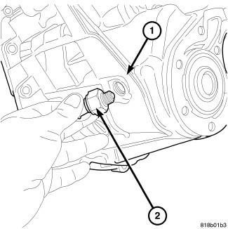
- Remove the backup lamp switch (2).
1 - SNAP RING PLIERS 2 - SNAP RINGS - Remove two snap rings (2) retaining the output shaft and the input shaft to the bearings.
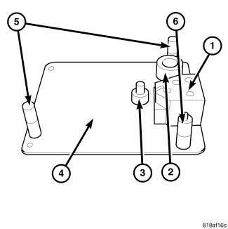
- The Bench Fixture (special tool #6785, Assembly, Pallet) (4) and adaptors (special tool #9761-1, Pad, Shift Rail Support) (1), (special tool #9761-2, Spacer) (3), (special tool #9761-3, Spacer) (2), (special tool #9761-6, Stand Off) (5) and (special tool #9761-7, Stand Off) (6) will be used to remove input and output shafts from the case.
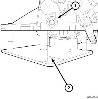
- Turn transaxle over. Install transaxle (1) onto Bench Fixture (special tool #6785, Assembly, Pallet) (2). Verify shim spacers and adaptors are in position on Bench Fixture (special tool #6785, Assembly, Pallet). Install transaxle into shop press.
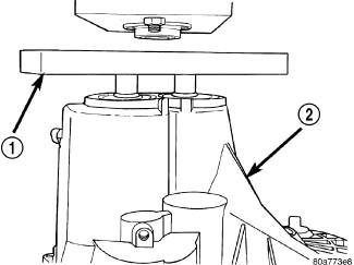
1 - BEARING FIXTURE 2 - TRANSAXLE CASE - Install Bearing Remover (special tool #6768, Remover, Bearings) (1) onto transaxle end bearings. Verify tool is properly aligned to input and output shafts.CAUTION:
The oil dams in the input and output shafts can be damaged while pressing on the shafts if the bearing fixture is not used properly.
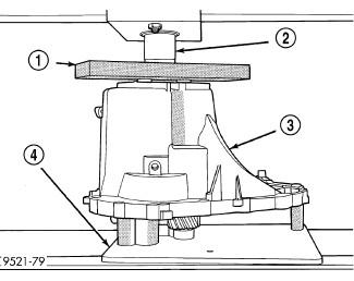
1 - BEARING FIXTURE 2 - PRESS RAM 3 - TRANSAXLE CASE 4 - BENCH FIXTURE - Install transaxle gear case (3) into shop press. Press (2) output and input shaft assemblies out of case.
- Remove transaxle from press.
- Carefully remove transaxle case (1) from the shaft assemblies and Bench Fixture (special tool #6785, Assembly, Pallet) (2).
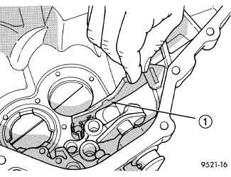
1 - OIL FEED TROUGH - Be sure the oil-feed trough (1) to the end bearings is not damaged.
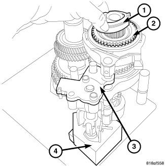
- Remove the reverse brake friction cone (1) from the input shaft assembly.
- Remove the blocking ring (2) from the input shaft assembly.
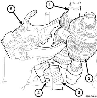
- Remove the shift blocker assembly, the reverse shift fork (5) and the detent assembly from the bench fixture (4).
- Remove input (2) and output shaft (1) assemblies from Bench Fixture (special tool #6785, Assembly, Pallet).
CAUTION:
The output shaft assembly is serviced as an assembly. Do not try to repair any component on the output shaft. If the 1-2 synchronizer or gear fails, it is necessary to replace the complete output shaft assembly.