Input Shaft, Transmission: Disassembly: Disassembly
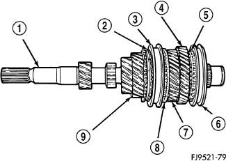
| 1 - INPUT SHAFT |
| 2 - STOP RING |
| 3 - SLEEVE |
| 4 - 5TH SPEED GEAR |
| 5 - STOP RING |
| 6 - SLEEVE |
| 7 - 4TH SPEED GEAR |
| 8 - STOP RING |
| 9 - 3RD SPEED GEAR |
Ring gaps must be measured with synchronizer ring biased towards gear clutching teeth on gear cone as much as possible while measuring gaps.
Before disassembly of the input shaft (1), it is necessary to check the synchronizer stop ring gap. Use a feeler gauge to measure the gaps between the stop rings (2, 5, and 8) and the speed gears. The correct gaps are listed below:
- 3rd - 0.73-1.53 mm (0.029-0.060 in)
- 4th - 0.77-1.57 mm (0.030-0.062 in).
- 5th - 0.73-1.53 mm (0.029-0.060 in)
- Reverse Brake - 0.505-1.74 mm (0.020-0.068 in.)
The reverse brake measurement is taken between the stop ring and case.
If a stop ring gap does not fall within the specifications, it must be inspected for wear and replaced. If the 1st or 2nd synchronizer stop ring is worn beyond specifications, the complete output shaft assembly must be replaced.
The input shaft incorporates the 3rd, 4th, and 5th speed gears and synchronizers on the assembly.
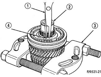
| 1 - SNAP RING PLIERS |
| 2 - INPUT SHAFT |
| 3 - BEARING SPLITTER |
| 4 - SNAP RING |
- Install Bearing Splitter (special tool #1130, Splitter, Bearing/Gear) (3) behind 5th speed gear. Remove snap ring (4) at 5th synchronizer hub on input shaft (2).
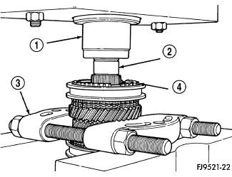
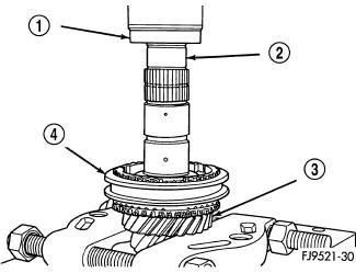
1 - PRESS RAM 2 - INPUT SHAFT 3 - BEARING SPLITTER 4 - SYNCHRONIZER ASSEMBLY - Remove synchronizer (4) and gear using shop press (1).
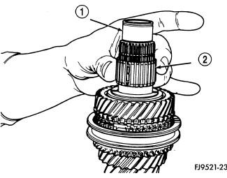
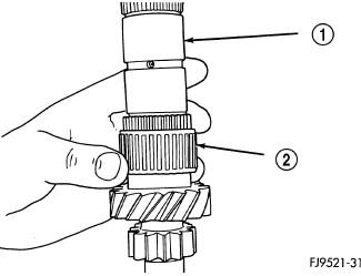
1 - INPUT SHAFT 2 - CAGED NEEDLE BEARING - Remove caged needle bearing (2).
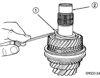
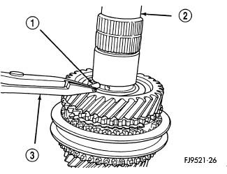
1 - SPLIT THRUST WASHER RING 2 - INPUT SHAFT - Remove 4-5 gears split thrust washer ring (1).
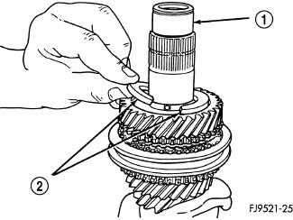
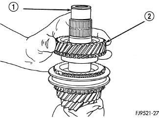
1 - INPUT SHAFT 2 - SPLIT THRUST WASHER - Remove split thrust washer (2).
1 - SEPARATION PIN 2 - INPUT SHAFT 3 - PLIERS - Remove split thrust washer separation pin (1).
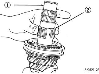
1 - INPUT SHAFT 2 - 4TH GEAR - Remove 4th gear (2).
1 - INPUT SHAFT 2 - CAGED NEEDLE BEARING - Remove 4th gear caged needle bearing (2). Check the caged needle bearing (2) for a broken retention spring.
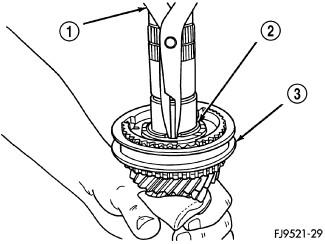
1 - SNAP RING PLIERS 2 - SYNCHRO SNAP RING 3 - SYNCHRONIZER ASSEMBLY - Remove blocking ring. Remove 3-4 synchronizer hub retaining snap ring (3).
1 - PRESS RAM 2 - INPUT SHAFT 3 - 3RD GEAR 4 - SYNCHRONIZER ASSEMBLY - Install input shaft in shop press (1). Using Bearing Splitter (special tool #1130, Splitter, Bearing/Gear), remove 3-4 synchronizer and 3rd gear (3).
1 - INPUT SHAFT 2 - 3RD GEAR CAGED NEEDLE BEARING - Remove 3rd gear caged needle bearing (2). Inspect needle bearing for a broken retention spring.
- Inspect the input shaft for worn or damaged bearing races or chipped gear teeth. Replace as necessary.