Diagnostic Test
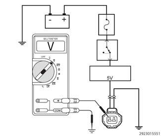
- TESTING A 5-VOLT SUPPLY CIRCUIT FOR VOLTAGE
- Turn the ignition off.
- Disconnect the sensor harness connector.NOTE:
Check connectors - Clean/repair as necessary.
- Turn the ignition on.
- Set the multimeter to measure DC voltage.
- Connect the negative lead of the multimeter to a known good ground.
- With the positive lead of the multimeter, carefully probe the 5-volt supply circuit.
Is the voltage between 4.7 and 5.2 volts?
Yes
- Go To 2
No
- Check the 5-volt supply circuit for an open or short to ground. For further assistance, perform the appropriate Sensor Reference Voltage DTC diagnostic procedure.
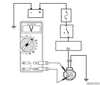
- TESTING A 5-VOLT SUPPLY CIRCUIT AND SENSOR GROUND CIRCUIT
- With the multimeter set to measure DC voltage.
- Move the negative lead of the multimeter to carefully probe the sensor ground or sensor return circuit in the harness connector.
- With the positive lead of the multimeter, carefully probe the 5-volt supply circuit.
Is the voltage between 4.7 and 5.2 volts?
Yes
- At this time the 5-Volt Supply and sensor ground circuit are working properly. Continue to measure the voltage between the wires, wiggle the wire harness and connectors while checking for an intermittent condition.
- Use the wiring diagram as a guide to trace the circuits and look for any in-line connectors where the open could occur intermittently.
- Look for any chafed, pierced, pinched, or partially broken wires.
- Look for broken, bent, pushed out or corroded terminals. Verify that there is good pin to terminal contact in the related wire harness connectors.
- Perform any Technical Service Bulletins (TSBs) that may apply.
No
- Repair the open or excessive resistance in the Sensor Ground (Sensor Return) circuit.