Low Frequency Moan Heard During First Brake Apply (05-003-16)
WARNING: This page is about the Compass High Altitude, 2.0L Eng VIN A, which is a different variant/trim than selected.
Publication date: 2016-08-20Reference number: 05-003-16
Supersedes refnos: 05-003-14, 05-003-14 REV. A
LOW FREQUENCY MOAN HEARD DURING FIRST BRAKE APPLY
TECHNICAL SERVICE BULLETIN
Reference Number(s): 05-003-16, Date of Issue:
August 20, 2016
Superceded Bulletin(s): 05-003-14 REV. A, Date of Issue:
December 20, 2014
| CHRYSLER: | 2012 - **2016** Jeep Compass / Patriot (MK) |
| GROUP: | Brakes |
NOTE:
THIS BULLETIN SUPERSEDES SERVICE BULLETIN 05-003-14 REV. A, DATED DECEMBER 20, 2014, WHICH SHOULD BE REMOVED FROM YOUR FILES. ALL REVISIONS ARE HIGHLIGHTED WITH **ASTERISKS** AND INCLUDE A NEW MODEL YEAR AND A NEW LOP.
SUBJECT
Low Frequency Moan Heard During First Brake Apply
OVERVIEW
This bulletin involves installing an anti-vibration bracket to the rear brake caliper.
MODELS
MODELS CHART
| 2012 - **2016** | (MK) | Jeep Compass / Patriot |
NOTE:
This bulletin applies to vehicles equipped with 4-Wheel-Disc Brakes (Sales Codes BRF) or (Sales Code BRG).
SYMPTOM/CONDITION
A low frequency moan is heard during the first brake apply when in reverse while the vehicle is cold or has been parked for several hours.
An audio sound file of the moan can be found in DealerCONNECT> TechCONNECT under: Service Info> 05 - Brakes> 05 - Brakes, Base> Diagnosis and Testing.
If the low frequency moan can be verified, the addition of the anti-vibration bracket may correct the condition.
DIAGNOSIS
If the customer describes the symptom, perform the REPAIR PROCEDURE .
PARTS REQUIRED
PARTS DESCRIPTION CHART
| Qty. | Part No. | Description |
|---|---|---|
| 1 | 68244275AB | Bracket Kit, Anti-Vibration. (Kit includes: 2 brackets, 8 bolts, and 4 nuts) |
REPAIR PROCEDURE
- Raise and support the vehicle. Refer to the detailed service procedures available in DealerCONNECT> TechCONNECT under: Service Info> 04 - Vehicle Quick Reference> Hoisting - Standard Procedure.
- Remove both rear tire and wheel assemblies for access. Refer to the detailed service procedures available in DealerCONNECT> TechCONNECT under: Service Info> 22 - Tires and Wheels> Removal.
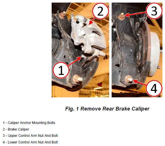
- Remove and discard the two bolts securing the disc brake caliper adapter to the brake backing plate (Fig. 1).
- Secure the brake caliper with caliper adapter out of the way (Fig. 1).
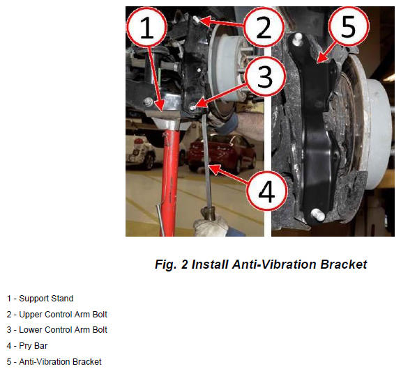
- Remove and discard the nuts securing the upper and lower control arms to the trailing link (Fig. 1). Do not remove bolts during this step.WARNING: To prevent personal injury and vehicle damage, use a suitable stand (1) to properly support suspension components while replacing the bolts (2 and 3) securing the control arms to the trailing link (Fig. 2).
- Remove and discard the bolt securing the upper control arm to the trailing link (Fig. 2). Install the NEW
bolt included with the anti-vibration bracket service kit.NOTE: It may be helpful to use a pry bar to align the bolt holes in the lower control arm and the trailing link (Fig. 2).
- Remove and discard the bolt securing the lower control arm to the trailing link (Fig. 2). Install the NEW bolt included with the anti-vibration bracket service kit.
- Install the anti-vibration bracket to the upper and lower control arm bolts (Fig. 2).
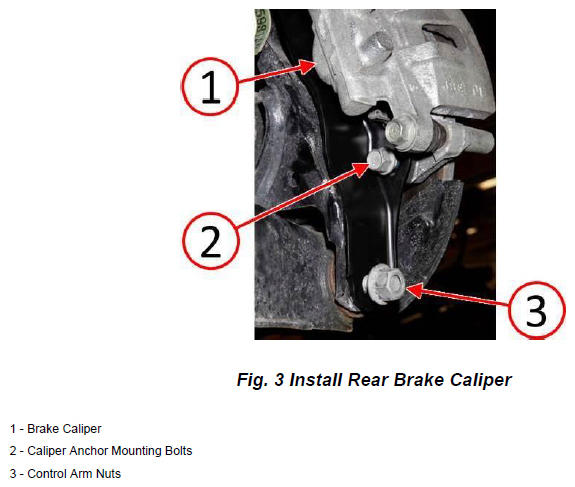
- Install the brake caliper with caliper adapter (Fig. 3).
- Install by hand but do not tighten both of the NEW longer caliper anchor mounting bolts included with the anti-vibration bracket service kit (Fig. 3).
- Install by hand but do not tighten
the NEW
upper and lower control arm nuts included with the anti-vibration bracket service kit (Fig. 3).CAUTION: Ensure there is NO gap between the anti-vibration bracket and trailing arm while tightening the control arm nuts and caliper mounting bolts. Any clearance may cause the anti-vibration bracket not to seat properly and may create a brake caliper to anti-vibration bracket clearance concern.
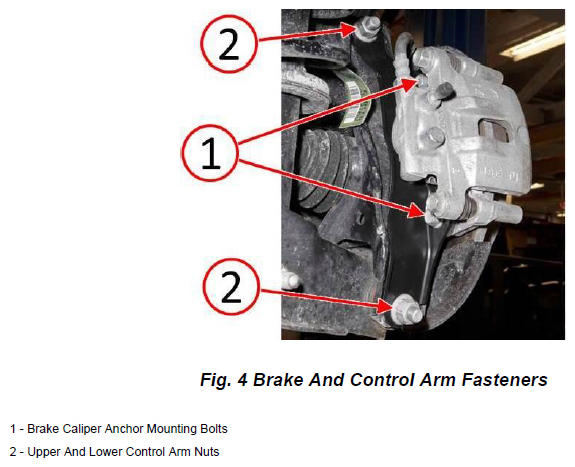
- Thread the upper and lower control arm nuts fully onto the bolts until no clearance remains between the nuts, anti-vibration bracket, and trailing arm. Do not tighten the nuts at this time
(Fig. 4).NOTE: The upper and lower control arm bolts/nuts will be tightened to specification at the end of the service procedure once the vehicle is resting at curb height in order to prevent preloading of the control arm bushings.
- Tighten the caliper anchor mounting bolts to 68 N.m (50 ft. lbs.) (Fig. 4).
- Repeat the anti-vibration bracket installation process Step # 3 through Step # 13 for the opposite side before continuing to Step #15. Installation of both right and left anti-vibration brackets requires the same process.
- Install both rear tire and wheel assemblies. Refer to the detailed service procedures available in DealerCONNECT> TechCONNECT under: Service Info> 22 - Tires and Wheels> Installation.
- Lower the vehicle.
- Position the vehicle on an alignment rack/drive-on lift. Raise the vehicle as necessary to access control arms mounting bolts and nuts.
- With the vehicle resting at curb height, tighten the bolts and nuts (2) securing the upper and lower control arms to the trailing link to 105 N.m (77 ft. lbs.) (Fig. 4).
POLICY
Reimbursable within the provisions of the warranty.
TIME ALLOWANCE
TIME ALLOWANCE CHART
| Labor Operation No: | Description | Skill Category | Amount |
|---|---|---|---|
| **05-85-05-9C | Install Anti-Vibration Bracket Kit (2 - Skilled) | 4 - Chassis Systems | 0.8 Hrs.** |
FAILURE CODE
FAILURE CODE CHART
| ZZ | Service Action |