Diagnostic Test
- CHECK FOR ACTIVE DTCS
- With the scan tool, read the active DTCs.
- Cycle the ignition switch from off to on at least 5 times, leaving the ignition on for a minimum of 90 seconds per cycle.
- With the scan tool, read the active DTCs.
Does the scan tool display this DTC as active?
Yes
- Go To 2
No
- If the DTC is stored, check for an intermittent condition. Visually inspect the related wiring harness connectors. Look for broken, bent, pushed out, or corroded terminals.
- Perform the BODY VERIFICATION TEST. Refer to STANDARD PROCEDURE - BODY VERIFICATION TEST .
- CHECK THE TOTALLY INTEGRATED POWER MODULE DTCs
- With the scan tool, read the Totally Integrated Power Module active DTCs.
Does the scan tool display any CAN B BUS DTCs - ACTIVE?
Yes
- Refer to DIAGNOSTIC CODE INDEX .
No
- Go To 3
- With the scan tool, read the Totally Integrated Power Module active DTCs.
- (D55) CAN B BUS (+) CIRCUIT OPEN
- Turn the ignition off.
- Disconnect the negative battery cable.
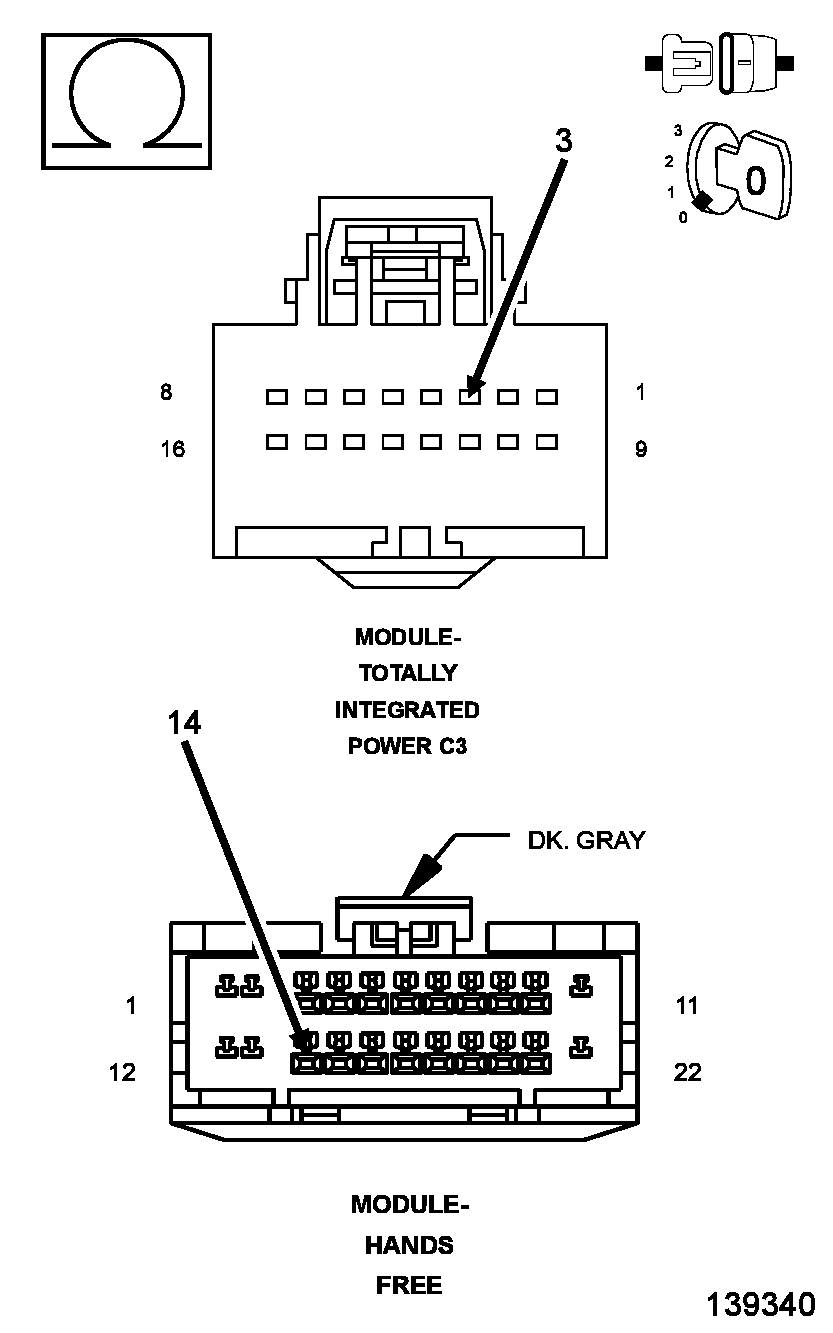
- Disconnect the Hands Free Module harness connector.
- Disconnect the Totally Integrated Power Module harness connector.
- Measure the resistance of the (D55) CAN B Bus (+) circuit between the Totally Integrated Power Module connector and the Hands Free Module connector.
Is the resistance below 2.0 ohms?
Yes
- Go To 4
No
- Repair the (D55) CAN B Bus (+) circuit for an open.
- Perform the BODY VERIFICATION TEST. Refer to STANDARD PROCEDURE - BODY VERIFICATION TEST .
- (D54) CAN B BUS (-) CIRCUIT OPEN
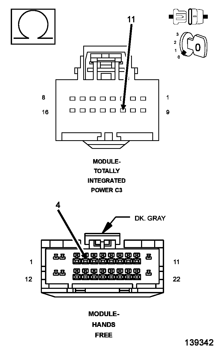
- Measure the resistance of the (D54) CAN B Bus (-) circuit between the Totally Integrated Power Module connector and the Hands Free Module connector.
Is the resistance below 2.0 ohms?
Yes
- Replace the Hands Free Module in accordance with the Service Information.
- Perform the BODY VERIFICATION TEST. Refer to STANDARD PROCEDURE - BODY VERIFICATION TEST .
No
- Repair the (D54) CAN B Bus (-) circuit for an open.
- Perform the BODY VERIFICATION TEST. Refer to STANDARD PROCEDURE - BODY VERIFICATION TEST .
- Measure the resistance of the (D54) CAN B Bus (-) circuit between the Totally Integrated Power Module connector and the Hands Free Module connector.