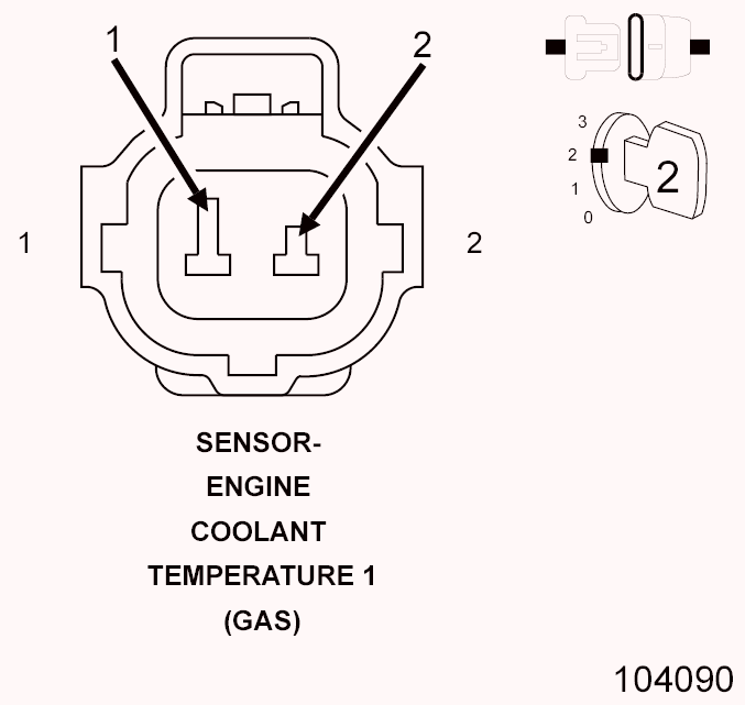
Diagnostic Test
- ACTIVE DTC NOTE:
Diagnose and repair any Engine Coolant Temperature (ECT) sensor DTCs before proceeding with this test.
NOTE:Inspect the ECT sensor and related PCM connector terminals for corrosion or damage.
NOTE:Extremely cold ambient temperatures may cause this DTC to set.
- Turn the ignition on.
- With the scan tool, select View DTCs.
- Review DTC information.
Is the Good Trip Counter greater than zero?
Yes
- Perform the INTERMITTENT CONDITION diagnostic procedure. Refer to STANDARD PROCEDURE .
No
- Go To 2
- LOW ENGINE COOLANT LEVEL
- Ignition on, engine not running.WARNING:
Allow the engine to cool before opening the cooling system. The system may be under pressure. Extreme burns or scalding may result. Failure to follow these instructions can result in possible serious or fatal injury.
- Inspect the cooling system for proper coolant level and condition.
Were any problems found?
Yes
- Inspect the vehicle for a coolant leak. Repair as necessary in accordance with the service information.
- Perform the POWERTRAIN VERIFICATION TEST. Refer to POWERTRAIN VERIFICATION TEST .
No
- Go To 3
- Ignition on, engine not running.
- THERMOSTAT
- Ignition on, engine not running.NOTE:
Allow the engine to cool to ambient temperature before proceeding with this test.
- Using the appropriate service information, determine the proper opening temperature of the thermostat.
- With a scan tool, read the ECT sensor value. If the engine was allowed to cool completely, the value should be approximately equal to the ambient temperature.
- Start the engine and allow it to reach operating temperature while monitoring the ECT sensor value. The sensor value change should be a smooth transition from start up to normal operating temperature. Monitor the actual coolant temperature with a thermometer.NOTE:
As the engine warms up to operating temperature, the actual coolant temperature (thermometer reading) and the coolant temperature value on the scan tool should be relatively close. The thermostat should not open until the engine reaches the temperature specified in the Service Information.
Does the thermostat open at the temperature specified in the Service Information?
Yes
- Go To 4
No
- Replace the thermostat in accordance with the Service Information.
- Perform the POWERTRAIN VERIFICATION TEST. Refer to POWERTRAIN VERIFICATION TEST .
- Ignition on, engine not running.
- CHECK THE (K2) ECT SIGNAL CIRCUIT FOR A SHORT TO VOLTAGE Fig 1: Measuring Voltage Of ECT Signal Circuit In Engine Coolant Temperature Sensor Harness Connector
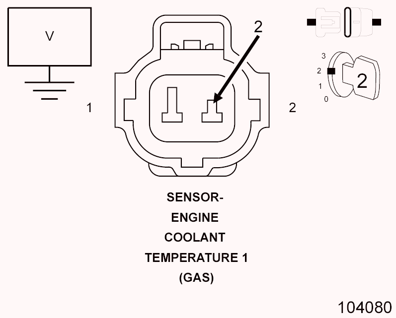 Courtesy of CHRYSLER GROUP, LLC
- Turn the ignition off.
- Disconnect the Engine Coolant Temperature Sensor harness connector.
- Turn the ignition on.
- Measure the voltage of the (K2) ECT Signal circuit in the Engine Coolant Temperature Sensor harness connector.
Is the voltage above 5.2 volts?
Yes
- Repair the (K2) ECT Signal circuit for a short to voltage.
- Perform the POWERTRAIN VERIFICATION TEST. Refer to POWERTRAIN VERIFICATION TEST .
No
- Go To 5
- CHECK THE (K2) ECT SIGNAL CIRCUIT FOR A SHORT TO GROUND Fig 2: Measuring Resistance Between Ground And ECT 1 Signal Circuit In Engine Coolant Temperature Sensor 1 Harness Connector
 Courtesy of CHRYSLER GROUP, LLC
- Turn the ignition off.
- Disconnect the PCM C2 harness connector.
- Measure the resistance between ground and the (K2) ECT Signal circuit in the Engine Coolant Temperature Sensor harness connector.
Is the resistance above 10k Ohms?
Yes
- Go To 6
No
- Repair the (K2) ECT Signal circuit for a short to ground.
- Perform the POWERTRAIN VERIFICATION TEST. Refer to POWERTRAIN VERIFICATION TEST .
- CHECK FOR THE (K2) ECT SIGNAL CIRCUIT SHORTED TO THE (K900) SENSOR GROUND CIRCUIT
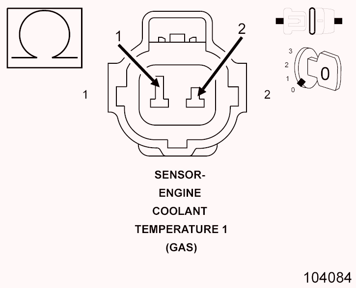 Courtesy of CHRYSLER GROUP, LLC
- Measure the resistance between the (K2) ECT Signal circuit and the (K900) Sensor Ground circuit in the Engine Coolant Temperature Sensor harness connector.
Is the resistance above 10k Ohms?
Yes
- Go To 7
No
- Repair the (K2) ECT Signal circuit for a short to the (K900) Sensor Ground circuit.
- Perform the POWERTRAIN VERIFICATION TEST. Refer to POWERTRAIN VERIFICATION TEST .
- Measure the resistance between the (K2) ECT Signal circuit and the (K900) Sensor Ground circuit in the Engine Coolant Temperature Sensor harness connector.
- CHECK THE (K2) ECT SIGNAL CIRCUIT FOR AN OPEN/HIGH RESISTANCE CAUTION:
Do not probe the PCM harness connectors. Probing the PCM harness connectors will damage the PCM terminals resulting in poor terminal to pin connection. Install the GPEC Diagnostic Adaptor to perform the diagnosis.
- Connect the (special tool #10436, Adapter, GPEC Diagnostic).
- Measure the resistance of the (K2) ECT Signal circuit between the Engine Coolant Temperature Sensor harness connector and the GPEC Adaptor.
Is the resistance below 5.0 Ohms?
Yes
- Go To 8
No
- Repair the (K2) ECT Signal circuit for an open or high resistance.
- Perform the POWERTRAIN VERIFICATION TEST. Refer to POWERTRAIN VERIFICATION TEST .
- CHECK THE (K900) SENSOR GROUND CIRCUIT FOR AN OPEN/HIGH RESISTANCE
- Measure the resistance of the (K900) Sensor Ground circuit between the Engine Coolant Temperature Sensor harness connector and the GPEC Adaptor.
Is the resistance below 5.0 Ohms?
Yes
- Go To 9
No
- Repair the (K900) Sensor Ground for an open or high resistance.
- Perform the POWERTRAIN VERIFICATION TEST. Refer to POWERTRAIN VERIFICATION TEST .
- Measure the resistance of the (K900) Sensor Ground circuit between the Engine Coolant Temperature Sensor harness connector and the GPEC Adaptor.
- ENGINE COOLANT TEMPERATURE SENSOR
- Turn the ignition off.
- Reconnect the PCM C2 harness connector.
- Connect a jumper between the (K900) Sensor Ground circuit and the (K2) ECT Signal circuit in the Engine Coolant Temperature Sensor harness connector.
- Turn the ignition on.
- With the scan tool, read the Engine Coolant Temperature Sensor signal voltage.
Is the voltage below 0.1 volts with the jumper in place?
Yes
- Replace the Engine Coolant Temperature Sensor in accordance with the service information.
- Perform the POWERTRAIN VERIFICATION TEST. Refer to POWERTRAIN VERIFICATION TEST .
No
- Go To 10
- POWERTRAIN CONTROL MODULE (PCM)
- Using the wiring diagram/schematic as a guide, inspect the wiring and connectors between the Engine Coolant Temperature Sensor and the Powertrain Control Module (PCM).
- Look for any chafed, pierced, pinched, or partially broken wires.
- Look for broken, bent, pushed out or corroded terminals.
- Monitor the scan tool data relative to this circuit and wiggle test the wiring and connectors.
- Look for the data to change or for the DTC to reset during the wiggle test.
- Perform any Technical Service Bulletins that may apply.
Were any problems found?
Yes
- Repair as necessary.
- Perform the POWERTRAIN VERIFICATION TEST. Refer to POWERTRAIN VERIFICATION TEST .
No
- Replace and program the Powertrain Control Module (PCM) in accordance with the service information. Refer to MODULE, POWERTRAIN CONTROL, REMOVAL .
- Perform the POWERTRAIN VERIFICATION TEST. Refer to POWERTRAIN VERIFICATION TEST .