Hub And Bearing: Removal: All-Wheel-Drive
NOTE:
Before proceeding, refer to WARNING .
- Raise and support the vehicle. Refer to HOISTING, STANDARD PROCEDURE .
- Remove the wheel mounting nuts (3), then the tire and wheel assembly (1).
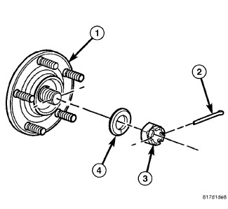
- Remove the cotter pin (2) from the hub nut (3) on the end of the axle half shaft.
- While a helper applies the brakes to keep the hub (1) from rotating, remove the hub nut (3) and washer (4) from the axle half shaft.
- Tap the end of the half shaft inward, loosening it from the hub and bearing.
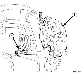
- Remove the disc brake caliper (2) lower guide pin bolt (1).
CAUTION:
When moving rear brake caliper upward, use extreme care not to damage or overextend the flex hose. Damage may occur.
- Rotate the caliper upward hinging off the upper guide pin bolt. Rotate the caliper upward just enough to allow brake rotor removal. Hang the caliper assembly in this position using wire or a bungee cord.
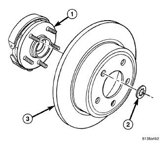
- Remove any clips (2) retaining the brake rotor (3) to the wheel mounting studs.
- Slide the brake rotor (3) off the hub and bearing (1).
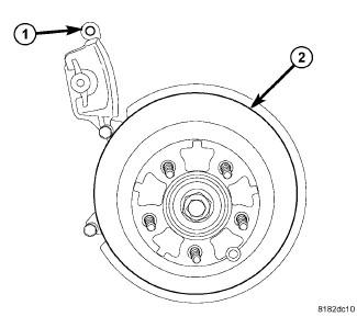
- Unclip the wheel speed sensor head (1) from the retainer on the rear of the hub and bearing (2).
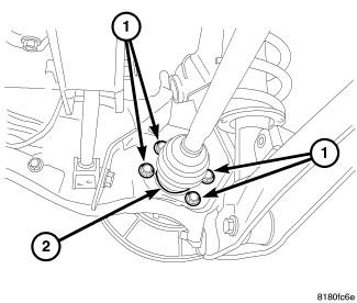
- Remove the four bolts (1) securing the hub and bearing (2) to the trailing link.
- Remove the hub and bearing.