Gas Engine
- Install the ICU with bracket (1) through the opening between the A/C lines and the exhaust manifold using the opposite of how it was removed.
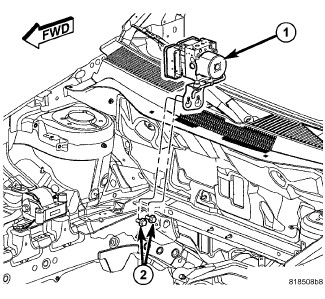
- Place the mounting bracket for the ICU (1) over the mounting screws (2) and hang the assembly in place. Tighten the two mounting screws (2) to 23 N.m (17 ft. lbs.).
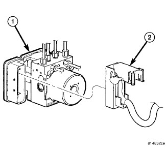
1 - ABM (PART OF ICU) 2 - WIRING HARNESS CONNECTOR CAUTION:Before installing the ABM harness connector on the ABM, be sure the seal is properly installed in the connector.
- Insert the ABM wiring harness connector (2) into the socket of the ABM (1) and close the cover, locking the connector in place.
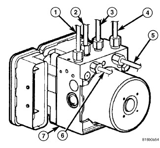
- Install the four chassis brake tubes (2, 3, 5, 6) brake tubes at the ICU hydraulic control unit (7). Tighten the tube nuts to 17 N.m (150 in. lbs.).
- Install the primary (4) and secondary (1) brake tubes at the ICU hydraulic control unit (7). Tighten the tube nuts to 17 N.m (150 in. lbs.).
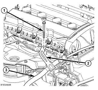
- Position the power steering pressure hose routing clamp (2) on the exhaust manifold and install the mounting screw (1). Tighten the mounting screw to 9 N.m (80 in. lbs.).
- Push the brake tube bundle routing clips (with tubes) onto the studs on the dash panel.
- Install the heat shield on the dash panel and tighten the lower and upper mounting nuts.
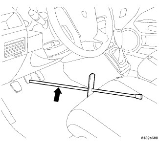
- Remove the brake pedal holding tool.
- Install the engine appearance cover.
- Connect the battery negative cable to the battery post. It is important that this be performed properly.
- Hook up the scan tool to initialize the ABM and perform the following:
- Clear any faults.
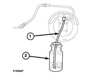
- Fill the master cylinder to the proper fill level and bleed the base and ABS hydraulic systems. Refer to STANDARD PROCEDURE - BASE BRAKE BLEEDING and STANDARD PROCEDURE - ANTILOCK BRAKE SYSTEM BLEEDING .
- Check for leaks.
- Perform the ABS Verification Test and road test the vehicle.